Lonten Tech
Custom STM32F407VET6 Minimum System Board Core Board Development Board Single Chip Microcomputer Experimental Board STM32
Custom STM32F407VET6 Minimum System Board Core Board Development Board Single Chip Microcomputer Experimental Board STM32
Couldn't load pickup availability
Introduction to Core Board Resources
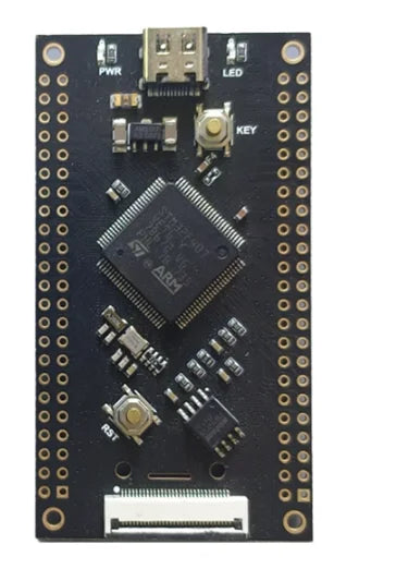
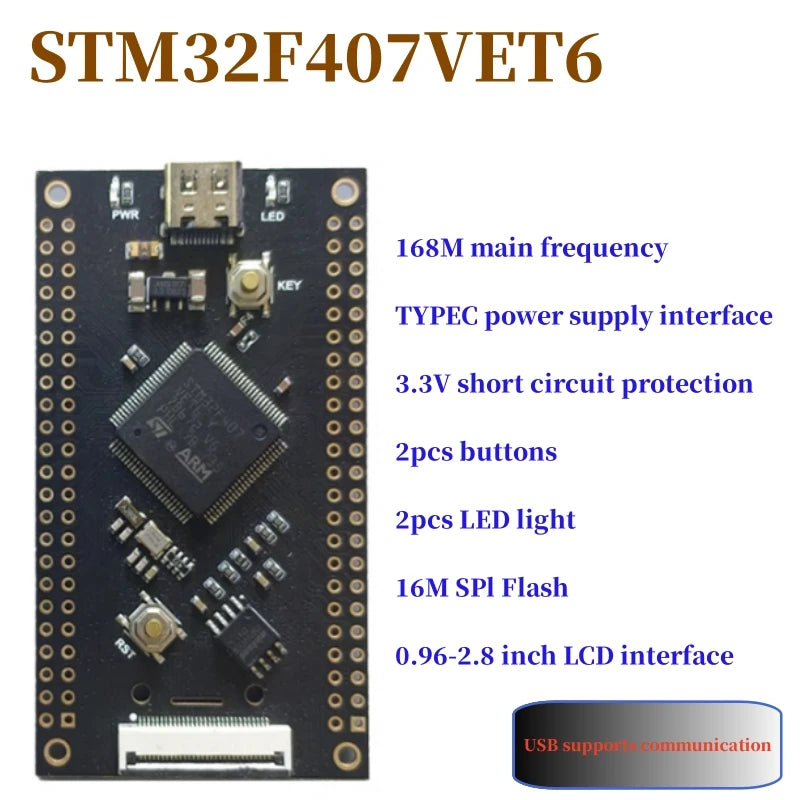
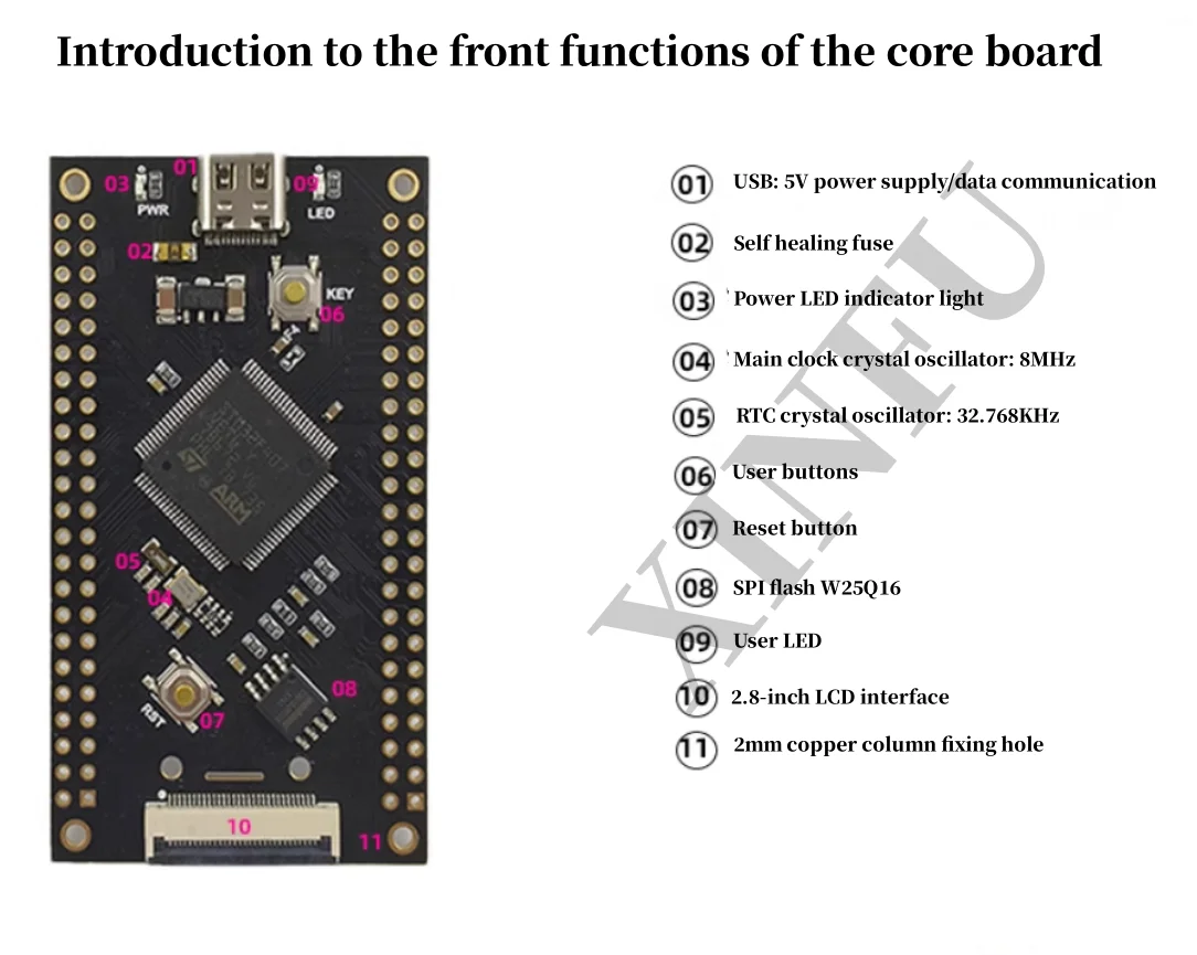
Main frequency: 168MHz, SPIflash: W25Q16
512Kb Flash SRAM 192KB inside the chip
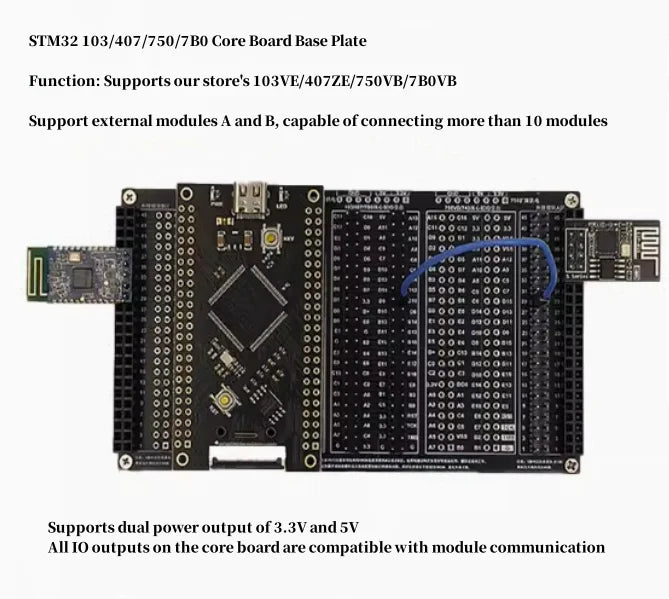
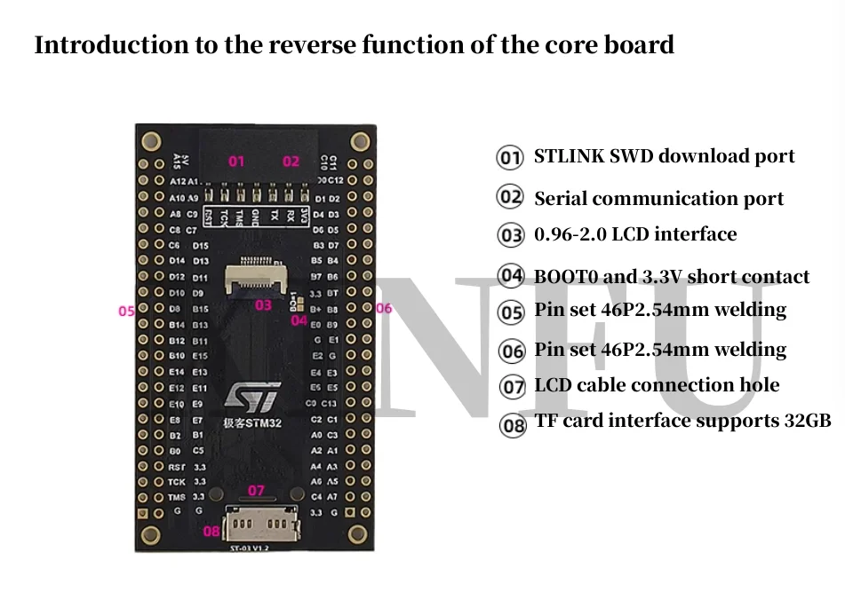
79 IO ports are led out by pin headers, with a pin spacing of 2.54mm
1 reset button, 1 user button
1 programmable LED, 1 power indicator light
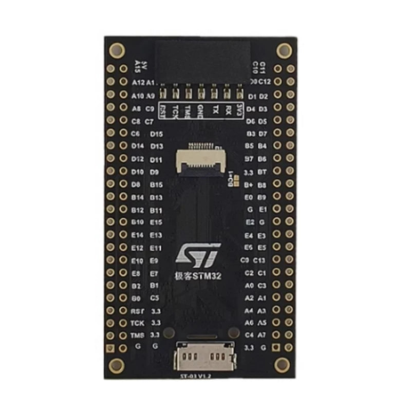
Output the SWD download port and serial port through the mother bus
Development of pin compatible universal board with a spacing of 2.54mm
Features: The download port supports pin and female insertion, making it easy to download
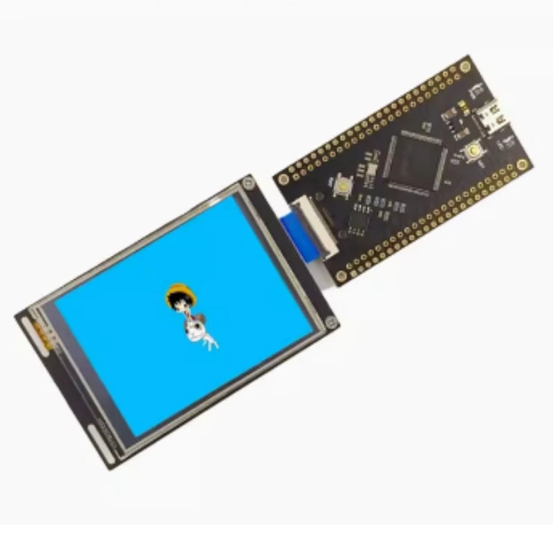
Onboard 0.96/1.54/1.69/2.0/2.8 LCD interface
Onboard SD card socket interface, supports up to 32GB, supports USB read/write
Motherboard Link LCD Display Experiment

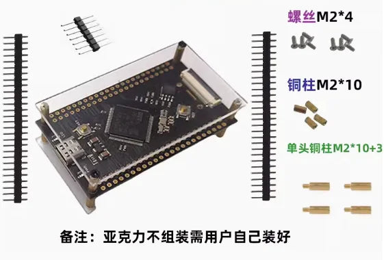
The motherboard can be assembled with copper pillars and a 1.69-inch LCD

Features: Core board needle can be inserted into universal board development

The needle spacing of the core board is 2.54mm, compatible with universal boards
Features: SWD download port with female plug design saves time

01. The download port adopts a pin to pin insertion method. Users only need to first insert the DuPont wire into the pin according to the wire sequence, and then insert the pin into the SWD pin of the motherboard
02. Connecting and debugging the serial port next to the download port is convenient
Pin definition for pin arrangement

Internal power diagram of the core board

Must see: Users recommend using 5V to power the development board, which can prevent the risk of damage to the STM32 chip or the entire development board caused by IO external short circuits. Many motherboards are damaged due to short circuits or input voltages exceeding 5V. In addition, the 3.3V output should not exceed 200mA when supplying power to external modules, otherwise it may cause the chip to overheat.


Share
