


Lonten Tech
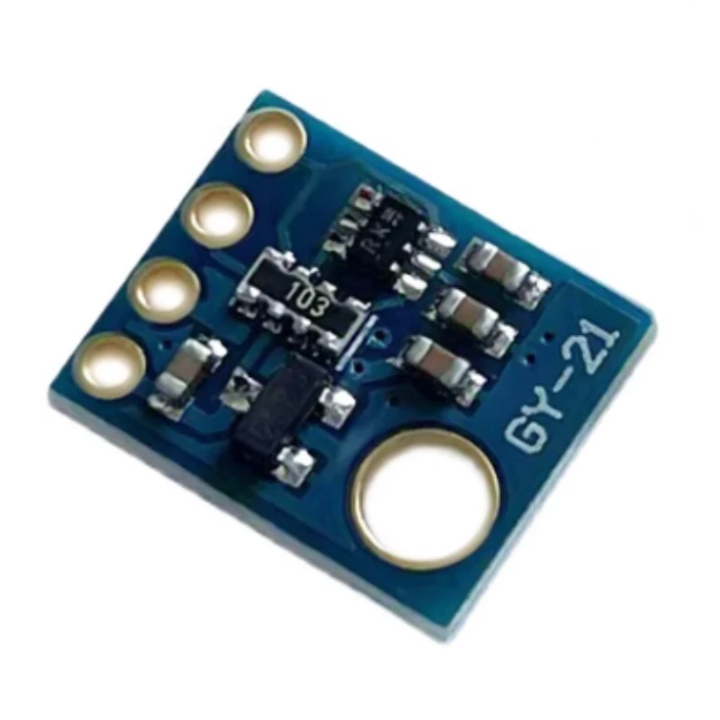
Custom GY-21 SHT21 HTU21D replaces SI7021 temperature and humidity sensor module I2C interface
Custom GY-21 SHT21 HTU21D replaces SI7021 temperature and humidity sensor module I2C interface
Couldn't load pickup availability
HTU21 Moisture Sensor
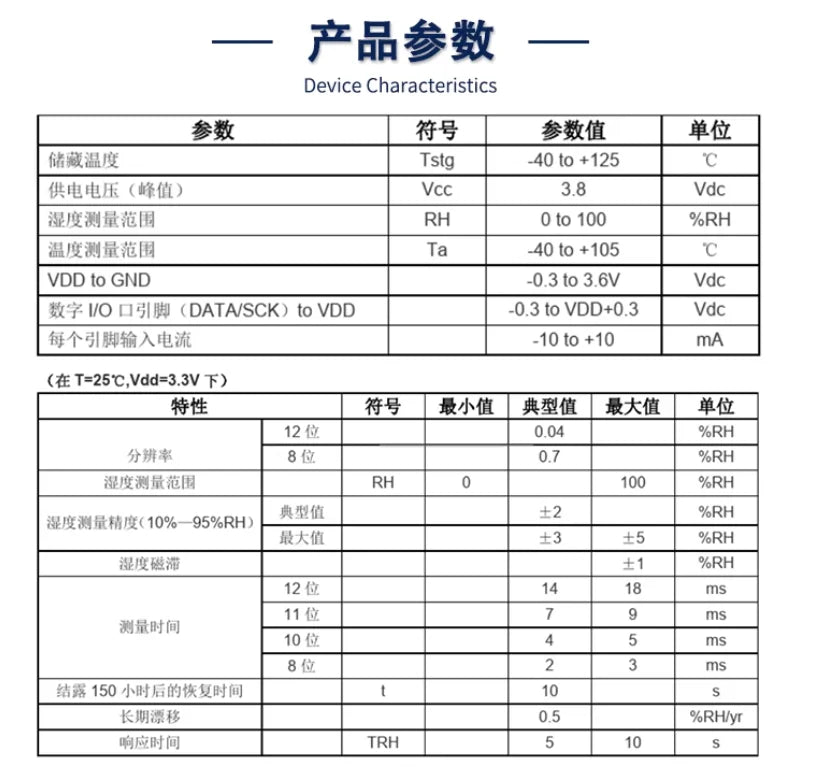
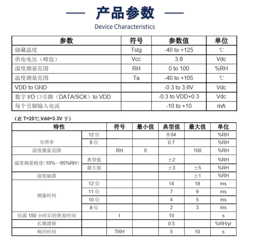
The new generation HTU21D temperature and humidity sensor has established new standards in terms of size and intelligence: it is embedded in a double row flat no pin DFN package suitable for reflow soldering, with a bottom surface of 3x3mm and a height of 1.1mm. The sensor outputs calibrated digital signals in standard I2C format. The HTU21D temperature and humidity sensor provides accurate and reliable temperature and humidity measurement data for 0EM applications. Temperature and humidity digital outputs are achieved through the interface and module connection of a microcontroller. The resolution of HTU21D can be changed by inputting commands (8/12 bit or even 12/14 bit RH/T), and the sensor can detect low battery status and output a checksum, which helps improve communication reliability.

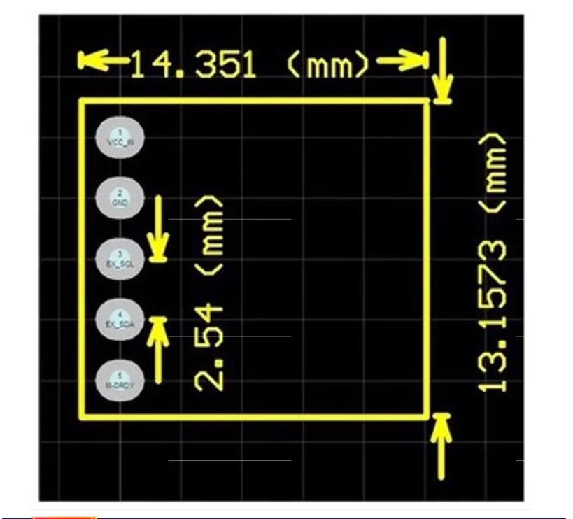
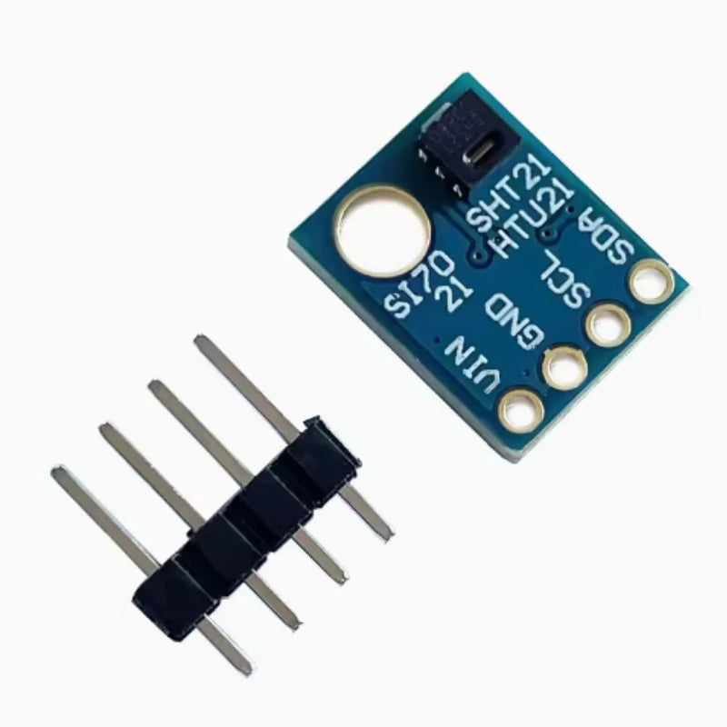
Pin Description
Power pin (VDD. GND)
The power supply range of HTU21 is 1.8VDC-3.6VDC, and the recommended voltage is 3.0V. A 0.1uF decoupling capacitor must be connected between the power supply (VDD) and ground (VSS), and the capacitor should be located as close as possible to the sensor.
Serial clock input (SCK)
SCK is used for communication synchronization between microprocessors and HTU21. Due to the interface containing completely static logic, there is no minimum SCK frequency.
Serial Data (DATA)
The DATA pin is a three state structure used to read sensor data. When sending commands to sensors, DATA must remain stable at the SCK high level when the effective target is on the rising edge of SCK. DATA changes after the falling edge of SCK. When reading data from sensors, DATA becomes valid after SCK decreases and remains valid until the falling edge of the next SCK. To avoid signal conflicts, the microprocessor should drive DATA at a low level. An external pull-up resistor (e.g. 10K Ω) is needed to pull the signal to a high level. The pull-up resistor is usually included in the I/O circuit of the microprocessor.
Design Description
If the SCL and SDA signal lines are parallel and very close to each other, it may cause signal crosstalk and communication failure. The solution is to place VDD or GND between two signal lines to separate them, or use shielded cables. In addition, reducing the SCL frequency may also improve the integrity of signal transmission. A 100nF decoupling capacitor must be added between the power pins (VDD, GND) for filtering. This capacitor should be placed as close as possible to the sensor.
data fetch
The default resolution set inside the sensor is 12 bits for relative humidity and 14 bits for temperature. The output data of SDA is converted into a two byte packet, with the high byte MSB placed first (left aligned). Each byte is followed by a response bit. The two status bits, namely the last two bits of LSB, must be set to '0' before performing physical calculations.