


Lonten Tech
Custom FT232HL USB to serial port JTAG openOCD Xilinx HS2 Manufacturer
Custom FT232HL USB to serial port JTAG openOCD Xilinx HS2 Manufacturer
Regular price
$100.00 USD
Regular price
$0.00 USD
Sale price
$100.00 USD
Unit price
per
Couldn't load pickup availability
The application board performs interface level conversion through the chip 74LVC1T45, and can support (1.8V-5V) level.
After the application board is set, it can be used as openOCD or Xilinx HS2 downloader.
For detailed functions of the chip, please refer to its datasheet.
【description】
Overall dimensions (length × width × height): 56 × 32 × 18 mm
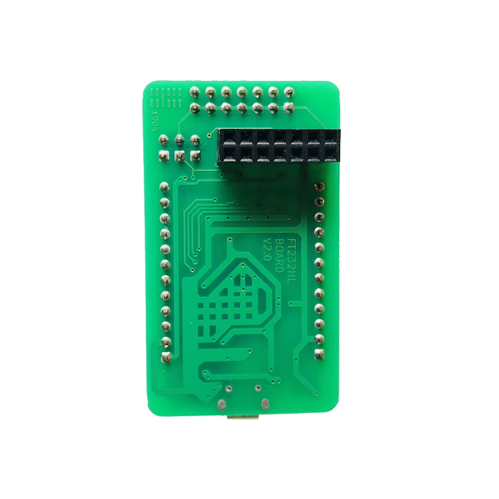
PCB size (length × width × thickness): 55 × 32 × 1.6 mm
Power supply mode: +5V, connected to CN3 via MicroUSB cable.
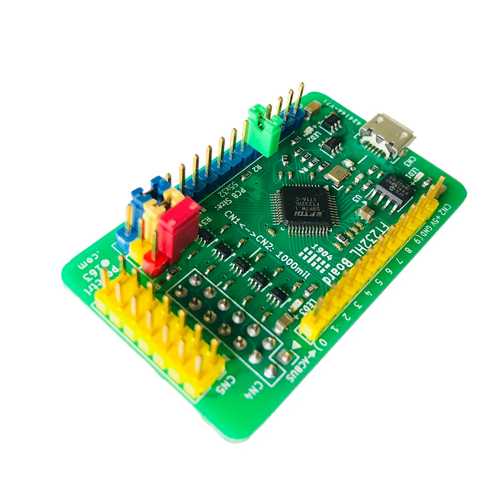
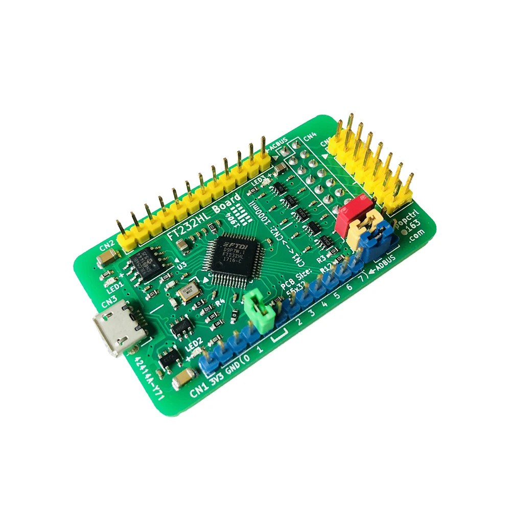
All function pins are all led out, which is convenient for connecting peripheral modules with DuPont wires.
An ESD protection circuit is added to the CN3 pin; the pin definitions of CN4 and CN5 are the same, and there is a level conversion circuit. Please refer to the schematic diagram for details.
CN1: 2.54mm pitch 1×12 Pin single row of needles;
CN2: 2.54mm pitch 1×12 Pin single row of needles;
CN4: 2.54mm spacing 2×7 Pin double row female (welded on the bottom of PCB);
CN5: 2.54mm pitch 2×7 Pin double row needle.
The distance between CN1 and CN2 is: 1000mil, that is, 10×2.54 = 25.4mm.
【Relevant information】
1. The schematic diagram of the board (Address: https://github.com/arm8686/FT232HL-Board).
2. For chip documentation and drivers, please go to the FTDI official website to download the updated version (official website address: http://www.ftdichip.com/).
3. "FT232HL Application Board Concise User Manual V0.1.pdf" and other documents:
link:
Extraction code:
Regarding more usage methods and functions of FT232HL, users are required to understand the application documents of FTDI Company. We do not have relevant technical support for the time being.
[Simple steps to use]
LED1 is the power-on indicator. After the power is supplied, it is always on.
LED2 is a 3.3V LDO working indicator. After the power is supplied, it is always on.
LED3 is the interface power indicator, which will only light up after the external interface provides power.
After installing its driver CDM21228_Setup, FT232HL defaults to USB to serial port.
The serial port debugging software on the PC can be used to test this serial port conveniently.
Hardware connection mode during test: Use jumper caps to short-circuit ADBUS0 and ADBUS1 to perform spontaneous transmission and self-reception tests.
U7 (74HC573) is connected to BDBUS and used to drive LED for signal indication.
When the board is powered on, some LEDs flicker, which is normal.
When BDBUS is used as a serial port and turned on, the red light in LED5 is always on. This is an indication of hardware flow control and is a normal phenomenon.
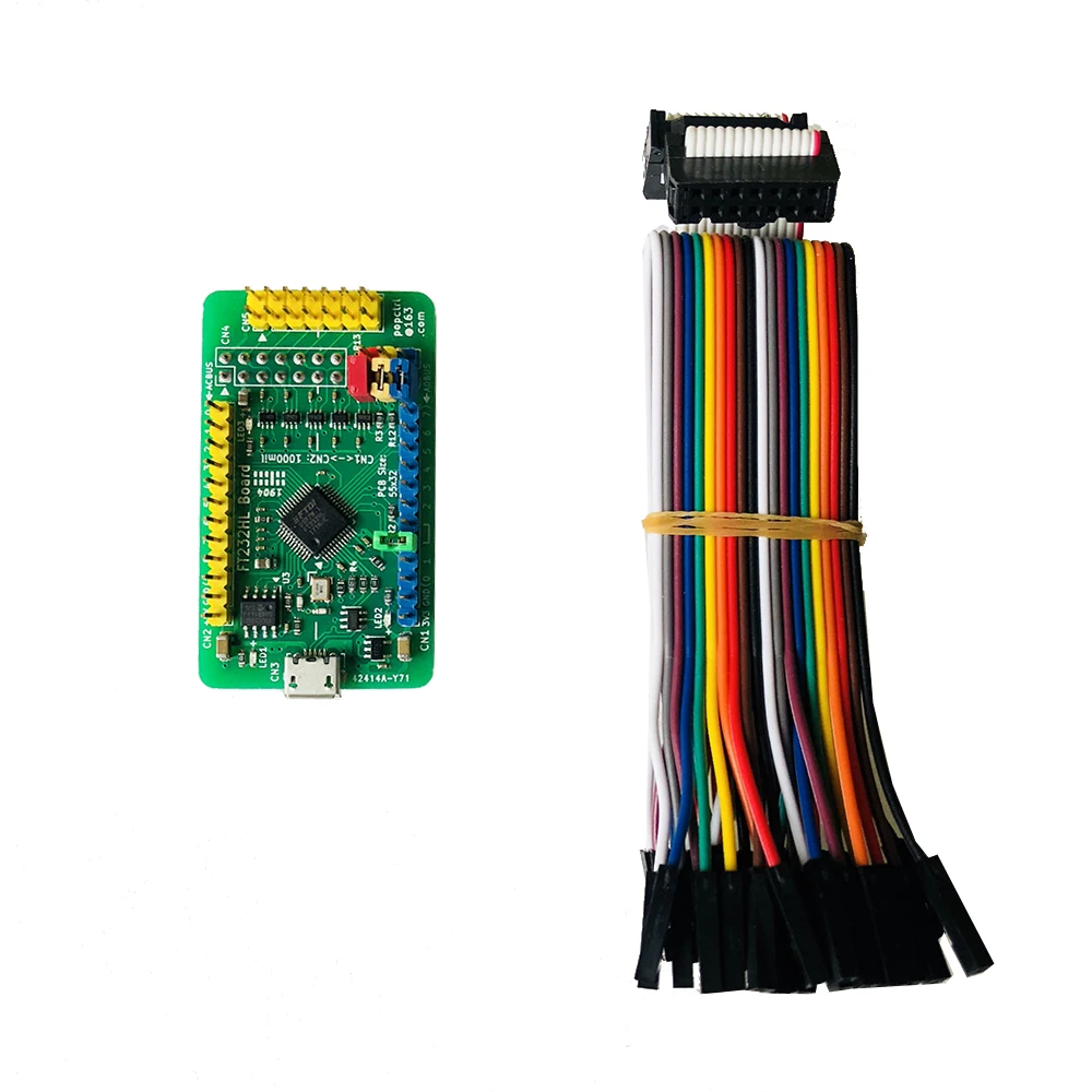
【Shipping list】
1. FT232HL application board: 1;
2. 14P gray cable (approximately 20cm in length, in the same direction): 1;
3. Dupont line: 10 lines.
[Also see]
FT2232HL Development Board/Application Board
http://item.taobao.com/item.htm?id=571105722642
FT4232HL Development Board/Application Board
http://item.taobao.com/item.htm?id=573554926815
CoLinkEx debug emulator
http://item.taobao.com/item.htm?id=552133347271
CP2102 module USB to TTL serial port
http://item.taobao.com/item.htm?id=580647073435
 Welcome Customize Order!