


Lonten Tech
Custom DSP PLL Digital Stereo FM Radio Receiver Module Board 87-108MHz With Serial Control Frequency Range 50Hz-18KHz Controller
Custom DSP PLL Digital Stereo FM Radio Receiver Module Board 87-108MHz With Serial Control Frequency Range 50Hz-18KHz Controller
Couldn't load pickup availability
Product features:
1: The use of advanced digital audio signal processing technology (DSP) and FM phase-locked loop modulation technology (PLL) to make the sound quality more realistic, more stable performance, long-term working frequency without deviation.
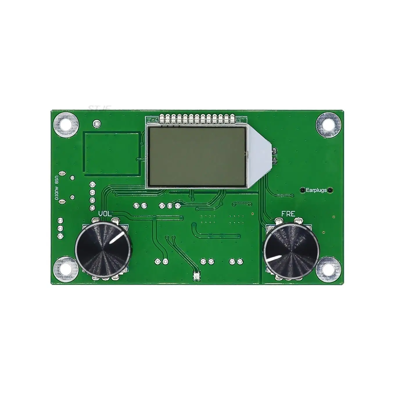
2: LCD display is more intuitive and accurate, with extremely low power consumption and minimal noise interference.
3: 30 level digital volume adjustment can be easily completed by pressing the button.
4: The data before power failure is automatically remembered.
5: Speaker/headset output automatically switches
6: The use of quartz crystal frequency stabilization, temperature change receiving frequency no longer drift.
7: The use of professional audio DSP for audio signal analysis and processing, no signal or weak signal FM bottom noise when the automatic silence, get rid of the traditional FM radio in no signal or weak signal when the annoying rustle.
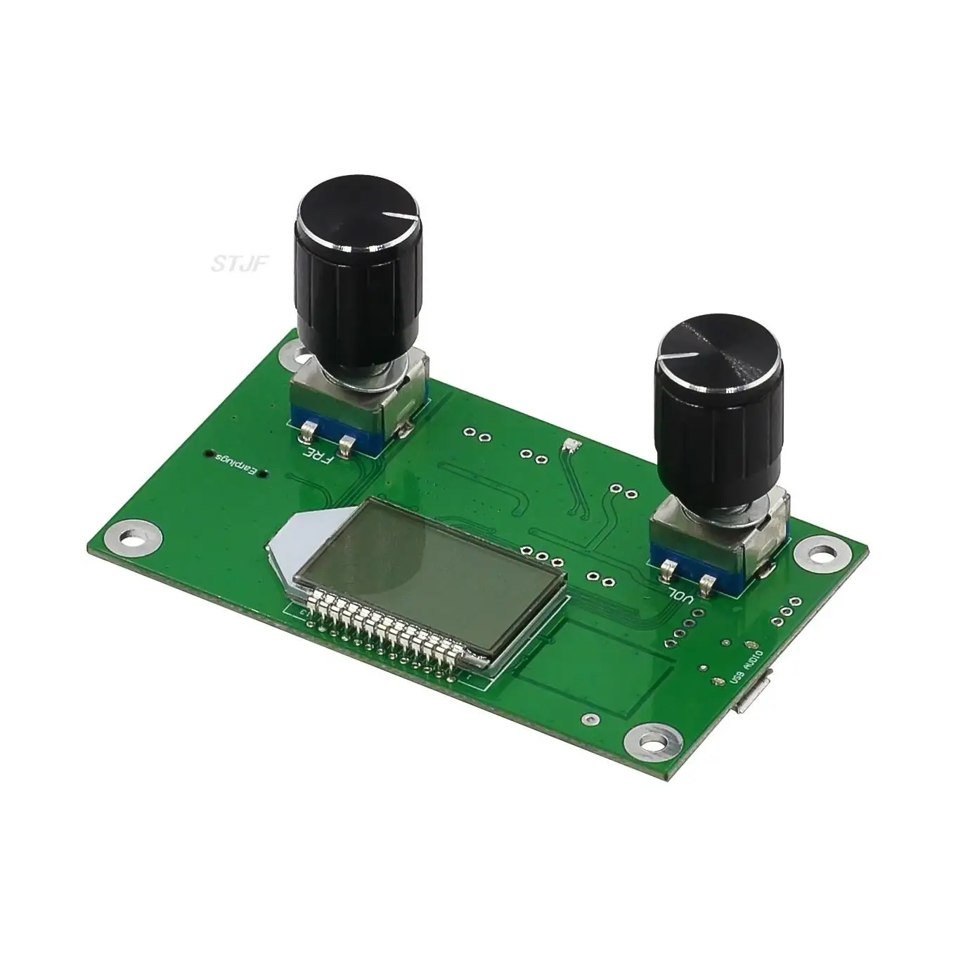
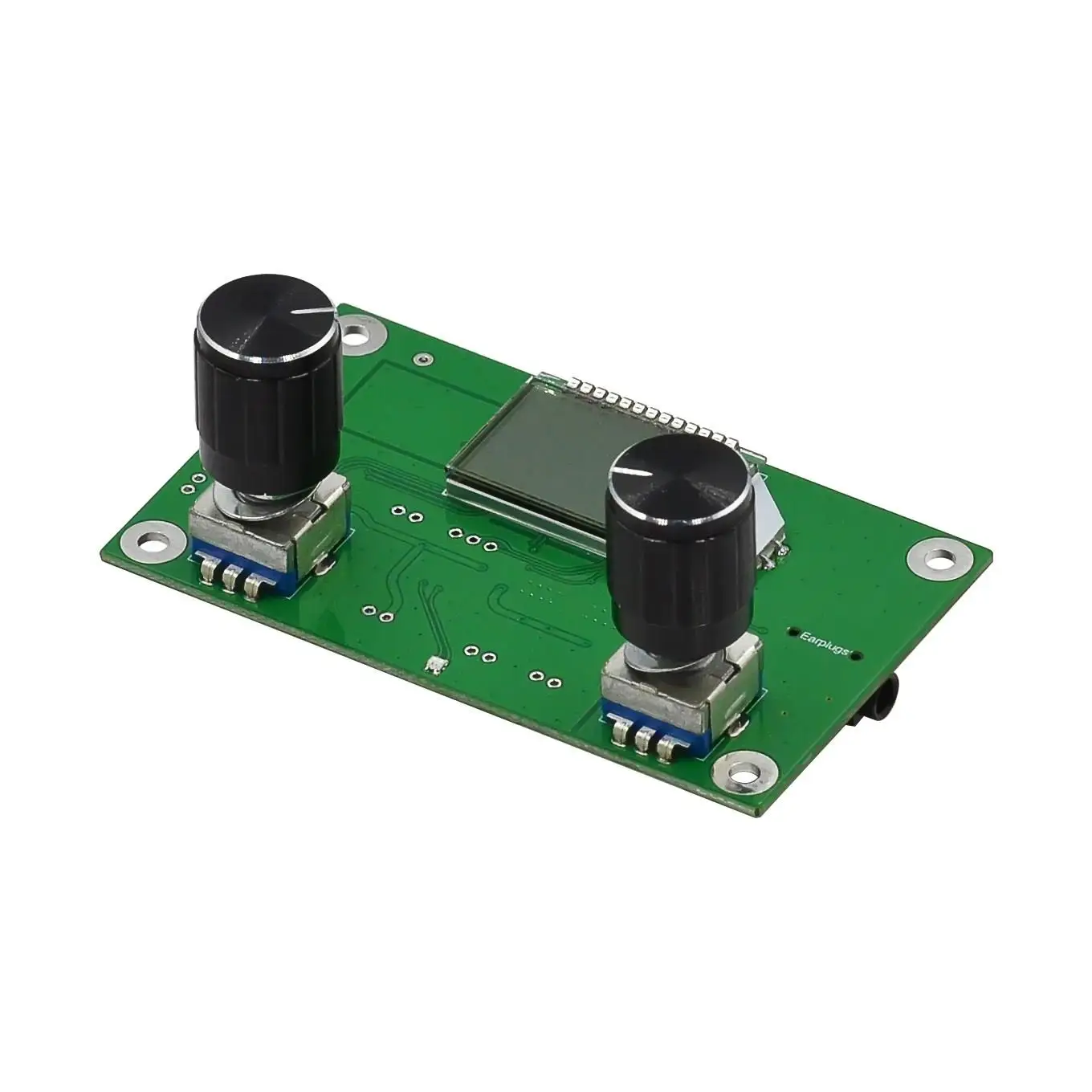
8: The use of incremental digital rotary encoder to adjust the volume and frequency, feel good, accurate positioning, stable and durable, 360° rotation without dead corners.
Level 9:30 digital volume adjustment range
10: Support serial communication control, can be used computer or MCU with serial device control module all functions.
Due to the limited page, if you want to know more details of this product, please go to the pottery plate to download ----
Technical manuals, specifications, operating instructions, etc........
http://pan.baidu.com/s/1nvaCzFV
Output power: 500mW (drive headset), 3Wx2 (drive speaker)
Frequency response range: 50Hz-18KHz
Receiving frequency range:
Shut down campus radio 87.0MHz-108.0MHz,
Enable the campus broadcast 76.0MHz to 108.0MHz
Equivalent noise: ≥30dB
Power supply voltage :3.0V-5.0V
Power supply current: maximum volume 1000mA, minimum volume 60mA(for reference only)
Track: Stereo
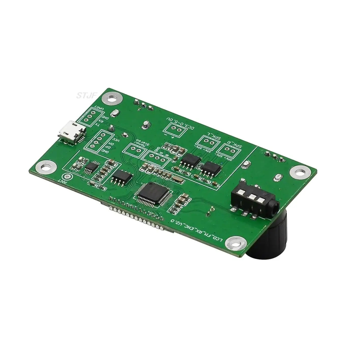
<1> : Power supply
The corresponding ports of the module (marked on the PCB board) -, + are respectively connected to the negative and positive terminals of the power supply (battery). It is recommended that the power supply use a battery or other regulated power supply. Do not use the switching power supply without filter (such as mobile phone charger, mobile power supply, and other switching power supply), otherwise the interference generated by the power supply will affect the normal operation of the module. The normal working voltage of this module is 3.0-5.0V, and the power supply voltage should not exceed this range. The maximum power supply current of this module is about 1A at the maximum volume, and the battery needs to be able to output enough current.
Note: A radio (any radio) is a radio sensitive device, and interference from the power supply or nearby may affect the normal operation of the module. Therefore, the power supply for the module is recommended to use the stable voltage obtained by the battery or power frequency transformer after voltage regulation. Do not use switching power supplies (such as mobile phone chargers, and any other switching power supplies), power banks, switching DC-DC converters, and can not have working class D amplifiers, microwave ovens and other devices that produce high frequency electromagnetic interference. Otherwise, the electromagnetic interference generated by these devices will be spatially coupled to the RF front end of the module, making the received restored signal produce noise.
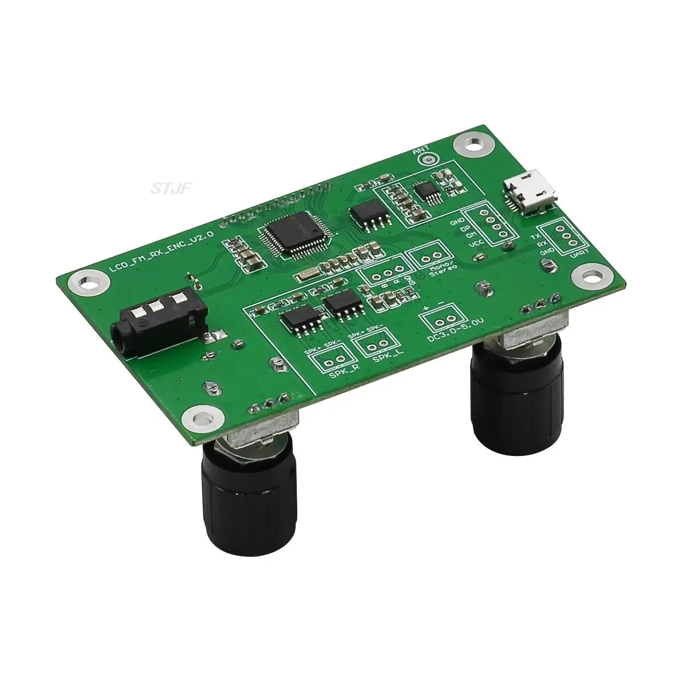
<2> : antenna
The FM_ANT port is used to connect the FM antenna. In order to better receive FM signals, it is recommended to connect an external 75cm drawbar antenna.
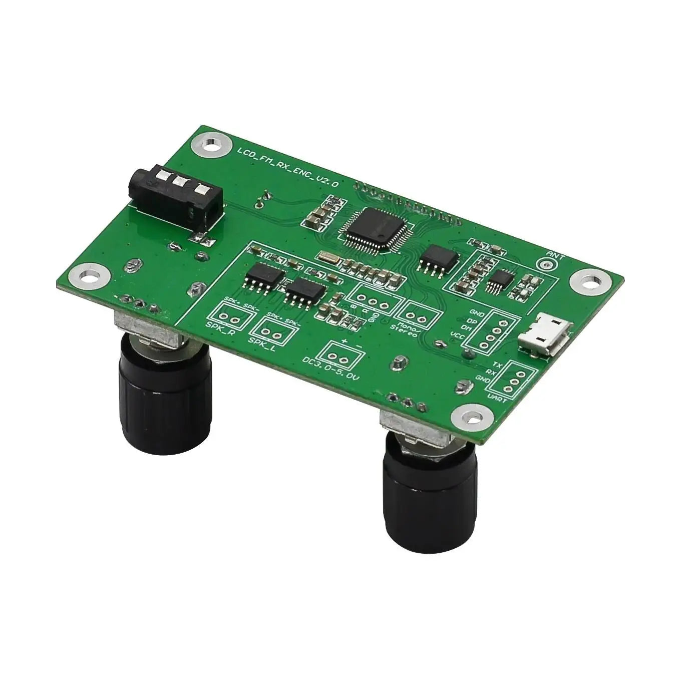
<3> : earphone/speaker output
This module comes with 3WX2 channel audio amplifier, if you need the speaker to access the speaker port, it is recommended to use 4Ω/3W speaker. If the headset is inserted, the audio automatically switches to the headset channel and the speaker channel automatically closes.
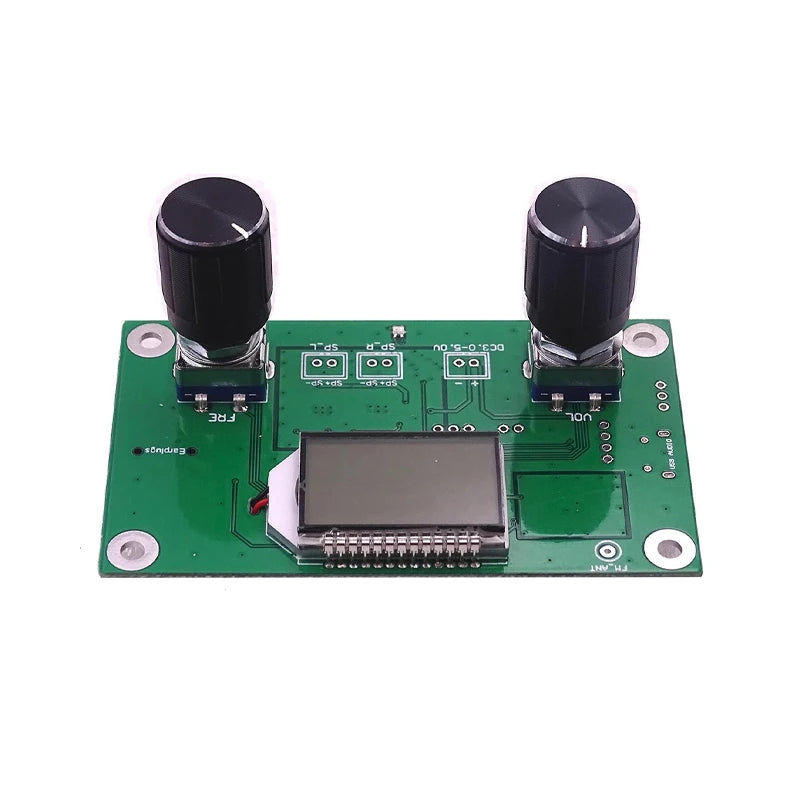
<4> Volume adjustment
Turn the VOL encoder to adjust the volume, while the LCD screen displays the volume level.
<5> Frequency regulation
Turn the FRE encoder to adjust the receiving frequency, while the LCD screen displays the current frequency, and press the encoder handle down to switch between silent and non-silent.
<6> Mute
To mute/unmute, press the VOL knob down
<7> Automatic noise switch
Press and hold down the FRE knob to switch ON or OFF the auto-static function. LCD subtitles on indicates that the auto-static function is turned on and off indicates that the auto-static function is turned off.
<8> Automatic noise threshold (threshold) adjustment (effective when the automatic noise switch is on)
Press the FRE button down to enter the auto-static and noise threshold adjustment screen. Users can adjust the action threshold of auto-static and noise according to the actual situation, the adjustment range is 0-20. The larger the value, the higher the threshold, and the weaker signal is more likely to be muted. On the contrary.
<9> : Serial port (no serial port control does not need to be connected)
The module reserves the TTL level serial port control interface. The communication between the TTL serial port and the module needs to connect the UART_RX, UART_TX and GND of the module (marked on the corresponding position of PCB). The external MCU (single chip microcomputer) or the serial port of the computer can be used to send instructions to control the related functions of the module. Note: Since the serial port level of the computer is not TTL level, it is necessary to connect the RS323 level to TTL electrical plain installation replacement device when connecting the computer communication or use the USB level to TTL level serial port module to communicate with this module. Because the serial command control module requires a certain amount of computer expertise, buyers who do not understand do not need to toss. All information see baby instructions, customer service does not provide technical guidance in this respect.
<10> : User Settings
This module can set the backlight status and whether to listen to the campus radio frequency band according to the specific use of the user. The setting method is as follows. In the power off state, press and hold down the VOL button to power on. LCD C1 indicates that campus broadcast is on. C0 indicates that campus broadcast is off. If the backlight is set, hold down the FRE button to power on the device. If B1 is displayed, the backlight is steady on. If B0 is displayed, the backlight is turned off for 20 seconds. Change the setting state Repeat this step to switch. The factory unified setting is not to open the campus broadcast frequency band, and the backlight is extinguished for 20 seconds without operation.
<11> : Stereo /mono switch terminal
The Stereo/mono terminal is used to set the FM receiving mode of the module. This terminal is suspended in stereo receiving mode and this terminal is mono receiving mode to ground.
Instructions:
The purpose of setting the Stereo/mono switch: Due to the different principles of stereo decoding and mono decoding, the decoding of stereo signals occupies a wide frequency band, and the signal quality is relatively high. Therefore, when listening to a relatively weak stereo broadcast, the signal-to-noise ratio will be very low, and more bottom noise will be generated. At this time, the circuit can be changed to mono receiving state to improve the signal-to-noise ratio of the output signal. Although there is no stereo effect in mono mode, the noise is relatively small, but the listening effect is better. In other words, this switch is used to improve the signal to noise ratio of the radio in the case of weak signal, switching to mono, can make the radio sound more clear in the case of weak signal, so the high-end FM Stereo radio is reserved for Stereo/mono switch to achieve stronger environmental adaptability.
Note: The factory default setting is to turn off the campus broadcast, the backlight is automatically extinguished without operation 20S, and the backlight is automatically noisy. The user can set it according to the specific situation.
Two: Precautions:
1: The power supply voltage must not exceed the power supply voltage range of the module.
2: Do not touch the back components of the module during work, so as not to affect the normal operation of the module or cause short circuit to burn the module.
Some basics about squelch:
Frequency discriminator demodulation is used in most FM receivers. The power spectrum of the output noise of the discriminator is parabolic and increases square with the increase of the output frequency. Therefore, when there is no useful input signal, the discriminator demodulated the noise with a larger output amplitude. These noises are amplified by the audio amplifier, and the output is very large "rustling" noise. In order to remove these noises, the FM receiver that transmits the speech has to add a squelch circuit, and when there is no input signal or the input signal is very weak, the squelch system turns off the audio output and keeps the headset quiet. A reliable squelch system is of great significance for FM receiver.
1. Common noise quieting methods and performance comparison
The squelch circuit system can be roughly divided into three categories: pilot squelch, noise squelch and carrier detection squelch. Before the transmitter modulates the voice signal, it usually adds a single tone at the low end of the voice signal frequency (below 300Hz), and then sends it to the modulation for transmission. After demodulation, the receiver detects this single tone and performs noise suppression control. Limited by the attenuation of the noise output and the degree of response of the transmitter circuit to the low frequency, the national military standard stipulates that the pilot frequency of **FM radio is 150 Hz (plus or minus 2Hz).
Noise squishing mode makes use of the phase discriminator's pressure and noise characteristics, when the RF signal is strong, the output noise is reduced; When the RF signal disappears, the output is large white noise. The noise squelch method uses this characteristic for squelch control. Generally, narrowband FM reception is equipped with an audio amplifier (noise extraction filter) and a simple Schmidt comparator for noise squelching, which is almost used in civilian FM receivers.
Carrier detection squelch is to use the current of the limiter circuit in front of the discriminator and the logarithm of the input signal strength in a considerable range, and the intensity of the input signal can be obtained by detecting this current, so as to carry out squelch control. Many FM receiving ics give this input signal strength signal (RSSI). This signal is commonly used as output signal strength meter driver, AGC, carrier detection squelch, etc.
Among the three silencing modes, the pilot silencing circuit is the most complex, and it has the advantages of strong anti-interference ability and simple operation. Noise squelch and carrier squelch circuits are simple, do not need to send additional pilot frequency, can achieve interoperability; Some stations often have both pilot and noise squelch functions to increase compatibility.
With the development of digital communication technology, more and more digital algorithms are applied to squelch detection. This module uses DSP device to realize FM audio signal sampling, and sends squelch flag bit to control the on-off of audio processing unit after operation in DSP.
The method of adjusting the noise of this module:
This module adopts DSP digital squelch and can control squelch threshold (threshold) flexibly by using software. The squelching threshold ranges from 0 to 20 levels. The lower the squelching threshold, the easier it is to receive radio signals with background noise. The higher the squelching threshold, the higher the noise threshold, and when the output noise is higher than the set value, the auto-static noise is turned on to mute the output. Therefore, when adjusting the squelch threshold, according to the use of the situation, if you want to hear the weak signal squelch threshold is lowered, if you want to hear the strong signal, the number is raised. Note that the noise squelch function cannot remove the background noise in the signal, but only controls the output silence by judging that the noise size of the signal exceeds the set threshold.