


Lonten Tech
Custom DC 2.4V~5.5V US-100 Ultrasonic Sensor/Ultrasonic Ranging Module with Temperature
Custom DC 2.4V~5.5V US-100 Ultrasonic Sensor/Ultrasonic Ranging Module with Temperature
Couldn't load pickup availability
High precision module, blind zone (2cm), stable ranging
1) Use voltage: DC5V
2) Static current: less than 2mA
3) Level output: high 5V
4) Level output: bottom 0V
5) Induction Angle: no more than 15 degrees
6) Detection distance: 2cm-450cm
7) High precision: up to 1mm
A control port sends a high level of more than 10US, and it can wait for a high level output at the receive port. As soon as there is an output, you can open the timer, when the port becomes low power, you can read the value of the timer, at this time for the distance time, you can calculate the distance. This continuous periodic measurement can reach the value of your moving measurement ~~
(1) Use IO trigger ranging to give at least 10us high level signal;
(2) The module automatically sends 8 40khz square waves to automatically detect whether there is a signal return;
(3) A signal is returned, and a high level is output through IO, and the duration of the high level is the time of the ultrasonic wave from transmission to return. Test distance =(high level time * speed of sound (340M/S))/2;
summarize
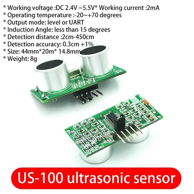
US-100 ultrasonic ranging module can realize the non-contact ranging function of 2cm~4.5m, has a wide voltage input range of 2.4~5.5V, static power consumption is less than 2mA, comes with temperature sensor to correct the ranging results, and has GPIO, serial port and other communication methods, with a watchdog, stable and reliable work.
Electrical parameter |
US-100 ultrasonic ranging module |
Operating voltage |
DC 2.4V~5.5V |
Static current |
2mA |
Operating temperature |
-20~+70 degrees |
Output mode |
Level or UART (jumper cap selection) |
Induction Angle |
Less than 15 degrees |
Detection range |
2cm-450cm |
Detection accuracy |
0.3cm+1% |
Serial port configuration in UART mode |
Baud rate 9600, start bit 1, stop bit 1, data bit 8, parity none, flow control none. |
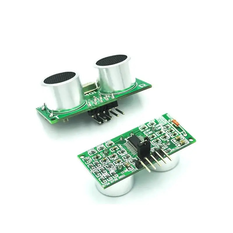
- This module physical drawing and size
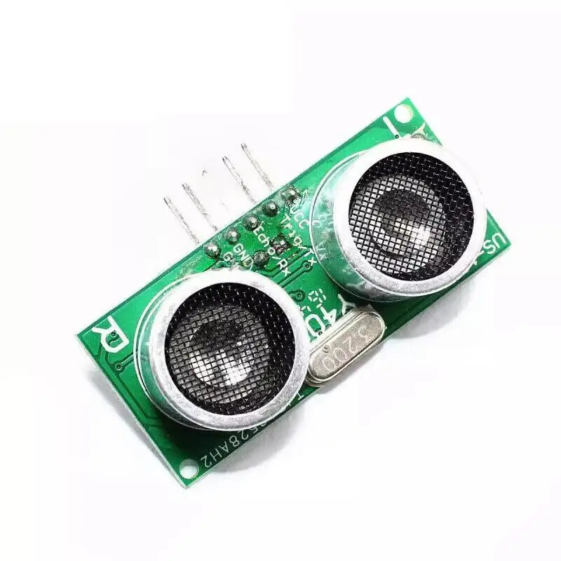
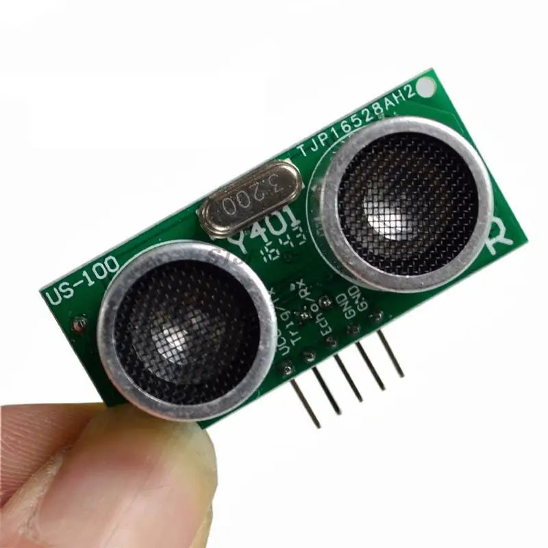
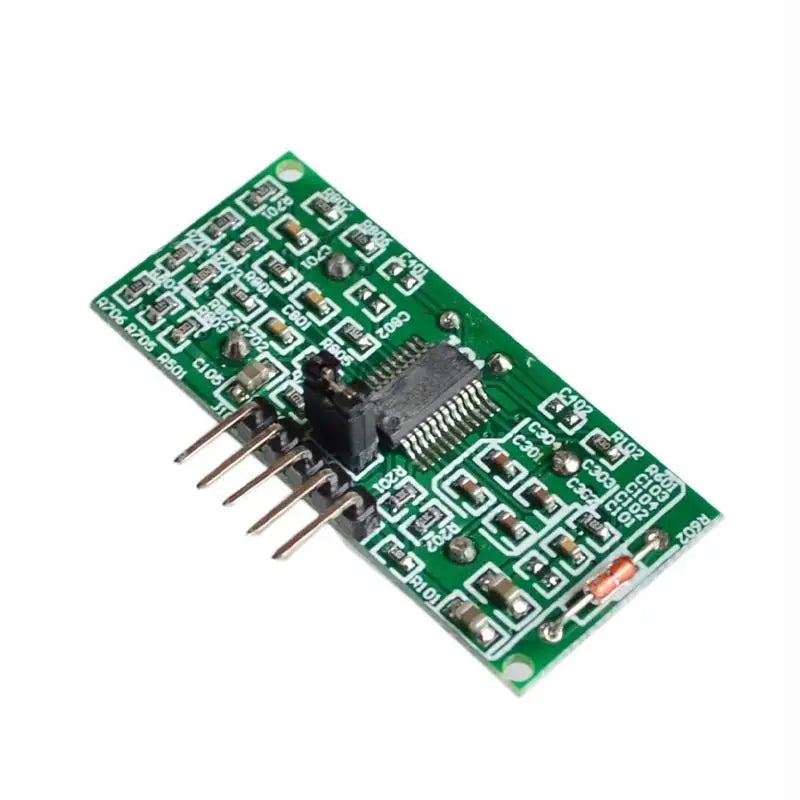
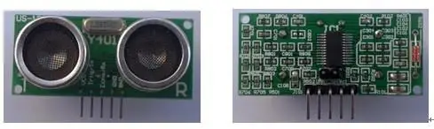
This module is shown in Figures 3.1 and 3.2:

Figure 3.1 Front view of the US-100 Figure 3.2 Back view of the US-100
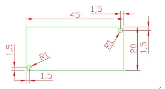
The size of this module: 45mm*20mm*1.6mm. There are two mechanical holes with a radius of 1mm on the board, as shown in Figure 3.3:
Figure 3.3: US-100 dimensions
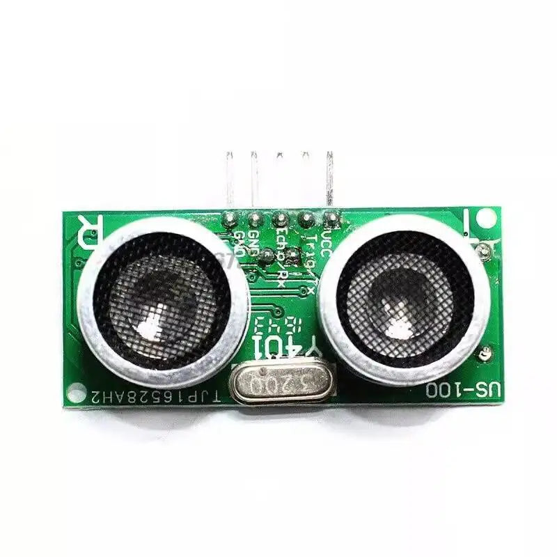
- Interface description
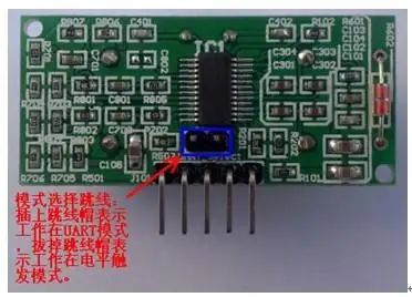
This module has two interfaces, namely mode selection jumper and 5 Pin interface. - Figure 4.1 shows the jumper interface for selecting the mode. Mode Select the jumper spacing is 2.54mm. When the jumper cap is inserted, the jumper mode is UART (serial port) mode. When the jumper cap is removed, the jumper mode is level trigger mode.
Figure 4.1: Mode selection jumper interface
The 5-PIN interface is a curved row of pins with 2.54mm spacing, as shown in Figure 4.2:
Figure 4.2:5 Pin interface
Numbers 1,2,3,4,5 from left to right. They are defined as follows:
Pin 1: Connect to VCC power supply (power supply range 2.4V~5.5V).
Pin 2: In UART mode, connect to the TX end of the external circuit UART; When in level trigger mode, connect the Trig end of the external circuit.
Pin No. 3: When in UART mode, connect the RX end of the external circuit UART; When in level trigger mode, connect the Echo end of the external circuit.
Pin 4: The place where the external circuit is connected.
Pin 5: The place where the external circuit is connected.
Working principle of level trigger ranging
Before the module is powered on, remove the jumper cap from the mode selection jumper so that the module is in level-triggered mode.
The timing of level triggered ranging is shown in Figure 5.1:
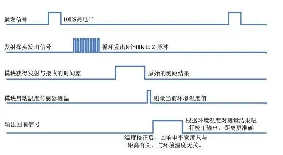
Figure 5.1: Timing diagram of US-100 ranging
Figure 5.1 shows that it is only necessary to input a high level of more than 10US in the Trig/TX pin, and the system can send eight 40KHZ ultrasonic pulses, and then detect the echo signal. When the Echo signal is detected, the module also measures the temperature value, and then corrects the ranging result according to the current temperature, and outputs the corrected result through the Echo/RX pin.
In this mode, the module converts the distance value to twice the time value at 340m/s, outputs a high level through the Echo terminal, and calculates the distance value according to the duration of this high level. That is, the distance value is (high level time *340m/s)/2.
Note: Because the distance value has been temperature corrected, it is no longer necessary to correct the ultrasonic speed according to the ambient temperature, that is, regardless of the temperature, the sound speed can be selected 340m/s.
Serial port trigger distance working principle
Before powering on the module, plug in the jumper cap of the mode selection jumper to enable the module to be in serial port trigger mode.
The timing of serial port triggered ranging is shown in Figure 6.1:
In this mode, you only need to enter 0X55 (baud rate 9600) in the Trig/TX pin, and the system can send eight 40KHZ ultrasonic pulses, and then detect the echo signal. When the Echo signal is detected, the module also measures the temperature value, and then corrects the ranging result according to the current temperature, and outputs the corrected result through the Echo/RX pin.
The output distance value consists of two bytes, one byte being the higher 8 bits of the distance (HDate), and the second byte being the lower 8 bits of the distance (LData), in millimeters. That is, the distance value is (HData*256 +LData) mm.
Figure 6.1: Serial trigger ranging timing diagram
Figure 6.1: Serial trigger ranging timing diagram

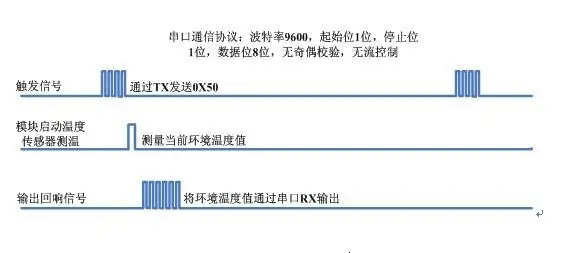
- Working principle of serial port triggered temperature measurement
Before powering on the module, plug in the jumper cap of the mode selection jumper to enable the module to be in serial port trigger mode. - Serial port triggered temperature measurement timing is shown in Figure 7.1:
- In this mode, you only need to enter 0X50 (baud 9600) in the Trig/TX pin, and the system will start the temperature sensor to measure the current temperature, and then output the temperature value through the Echo/RX pin.
- After measuring the temperature, the module returns a byte of temperature value (TData), the actual temperature value is TDATA-45. For example, if the RX receives 0X45 after sending 0X50 through TX, the temperature is [69 (the decimal value of 0X45) -45] = 24 degrees.