


Lonten Tech
Custom Compute Module IO Board Plus Composite Breakout Board for Raspberry Pi CM3/CM3L/CM3+/CM3+L Custom PCB ultrasonic cleanser pcba Manufacturer
Custom Compute Module IO Board Plus Composite Breakout Board for Raspberry Pi CM3/CM3L/CM3+/CM3+L Custom PCB ultrasonic cleanser pcba Manufacturer
Regular price
$100.00 USD
Regular price
$0.00 USD
Sale price
$100.00 USD
Unit price
per
Couldn't load pickup availability
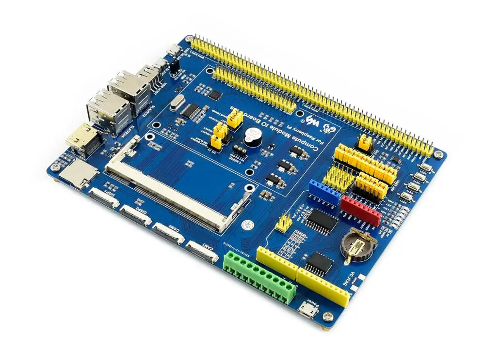
Compute Module IO Board Plus, Composite Breakout Board for Developing with Raspberry Pi CM3 / CM3L / CM3+ / CM3+L
Overview
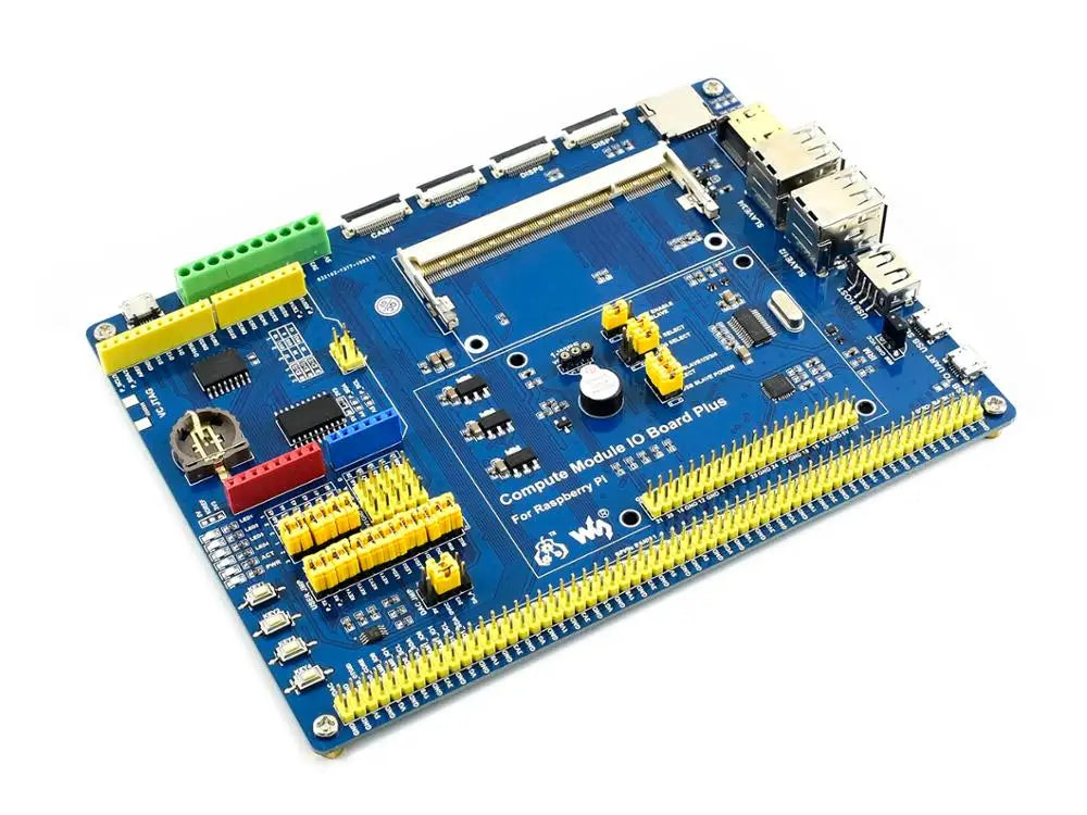
The Compute Module IO Board Plus is a development board which you can plug a Raspberry Pi Compute Module into, and make use of the resources of Pi more flexibly. It is compatible with the Compute Module IO Board V3 from the Raspberry Pi Foundation, along with various common use components.
Features
- Compatible with the Compute Module IO Board V3 from the Raspberry Pi Foundation
- Raspberry Pi GPIO header, for connecting sorts of Raspberry Pi HATs
- Ard connectivity, also supports Ard shields
- 1-WIRE interface, for connecting single-bus devices like DS18B20
- 4x keys, 4x LEDs, 1x Buzzer, for I/O testing
- Onboard USB HUB, allows connecting more USB devices
- IR receiver, IR remote control is available
- Onboard USB TO UART, for serial debugging
- Sensor interface
- 10-bit ADC, 38KSPS, 11-ch (6-ch for Ard interface, 5-ch for sensors)
- 16-bit DAC, 2-ch
- Onboard RTC, one of the most common and useful functions
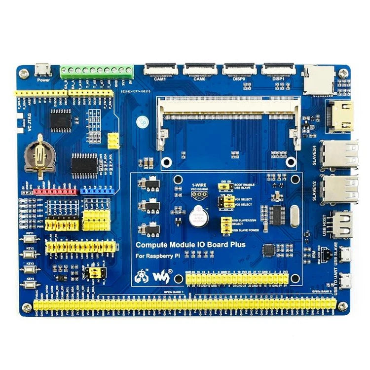
What's Onboard
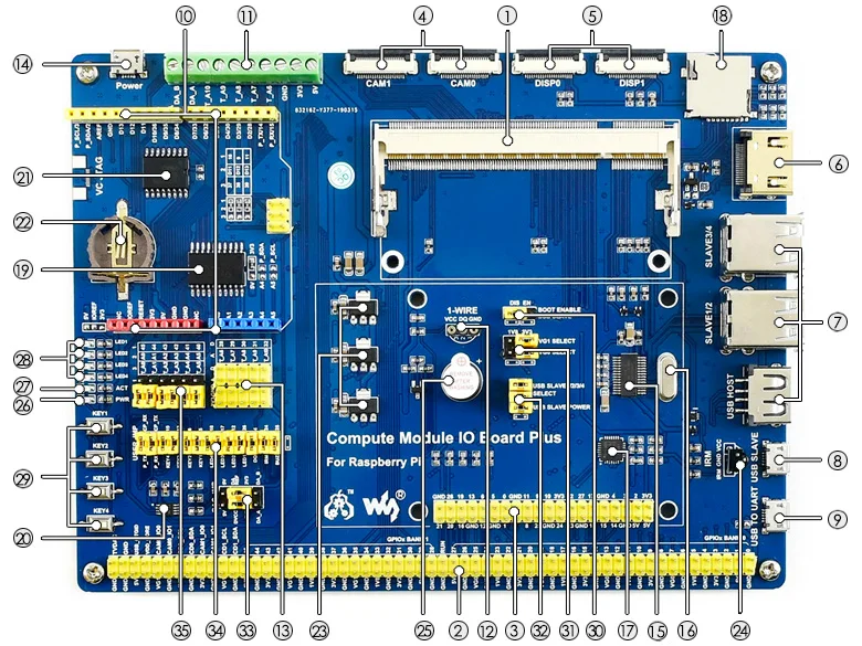
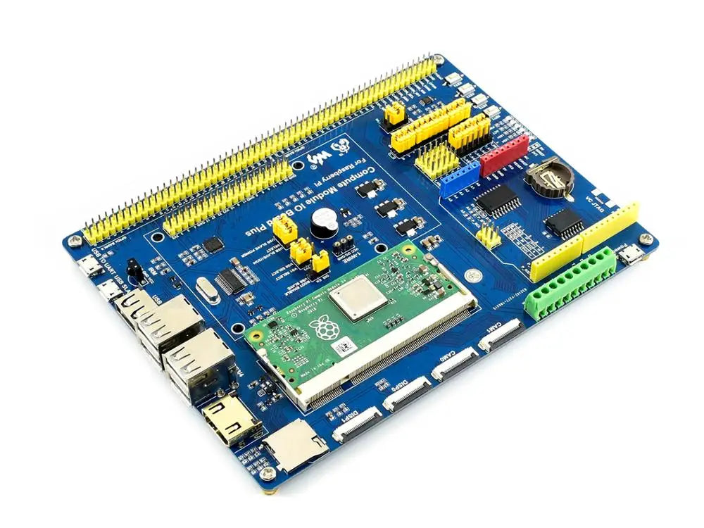
- Compute Module interface: for connecting Compute Module (CM3 / CM3L / CM3+ / CM3+L)
- Compute Module GPIO header: breakout all the Compute Module pins
- Raspberry Pi GPIO header: for connecting Raspberry Pi HATs
- CSI interface: camera ports, for connecting Raspberry Pi Camera
- DSI interface: display ports, for connecting Raspberry Pi LCD
- HDMI port
- USB ports: for connecting USB devices
- USB SLAVE interface: allows you to burn system image in to Compute Module 3
- USB TO UART interface: for serial debugging
- Ard header: for connecting Ard shields
- AD/DA input/output screw terminals
- 1-WIRE interface: for connecting single-bus devices like DS18B20
- Sensor interface
- Power port: 5V 2.5A
- FE1.1S: USB HUB chip
- 12MHz crystal
- CP2102: USB TO UART converter
- Micro SD card slot: insert a Micro SD card with pre-burnt system, to start up Compute Module 3 Lite
- TLC1543: AD converter
- DAC8552: 16-bit DAC, 2-ch
- DS3231: high-precision RTC chip, I2C interface
- RTC battery holder: supports CR1220 batteries
- Voltage regulator: 3.3V / 2.5V / 1.8V
- LFN0038K: IR receiver
- Buzzer
- Power indicator
- ACT indicator: indicating the Micro SD card status
- User LEDs
- User Keys
-
BOOT selection
- EN: enable the PC to access SD card/eMMC through USB SLAVE
- DIS: the Compute Module will boot from SD card/eMMC
- VGx power selection: config the I/O level
- USB HUB enable jumper: HUB enable and USB SLAVE power selection
- ADC/DAC configuration: config the power supply and reference voltage of ADC/DAC
- Peripheral configuration: config the control pins of UART, user keys, user LEDs, 1-WIRE interface, IR receiver, and buzzer
-
Ard AD selection
- connect 1 and 2: Ard A0-A5 as digital control pin
- connect 2 and 3: Ard A0-A5 as AD input
Dimensions
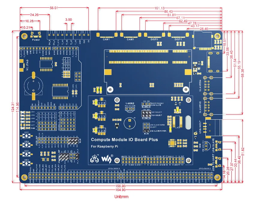
- Compute Module IO Board Plus x1