


Lonten Tech
Custom Custom Banana PI ESP32 S3 Low Power Microcontroller Development Board Support 2.4 GHz Wi-Fi For ESP-IDF MicroPython Manufacturer
Custom Custom Banana PI ESP32 S3 Low Power Microcontroller Development Board Support 2.4 GHz Wi-Fi For ESP-IDF MicroPython Manufacturer
Couldn't load pickup availability
The ESP32-S3 chip supports 2.4 GHz Wi-Fi and BT LE dual-mode wireless communication, the peripheral is compatible with low-power hardware design, and the power consumption in deep sleep mode is only 10uA.
It supports two power supply modes: USB and external 3.7V lithium battery, which can realize automatic power switching function under dual power supply, and supports USB charging mode. It can be directly applied to IoT low-power projects.
The development board supports ESP-IDF, Arduino, MicroPython and other methods for programming and development in terms of software.
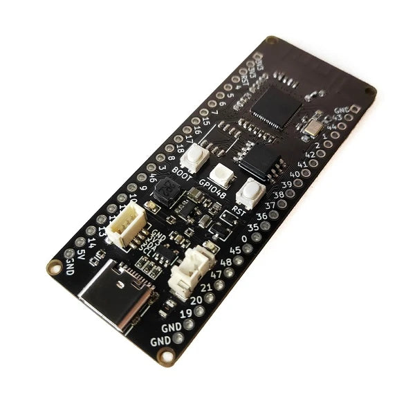
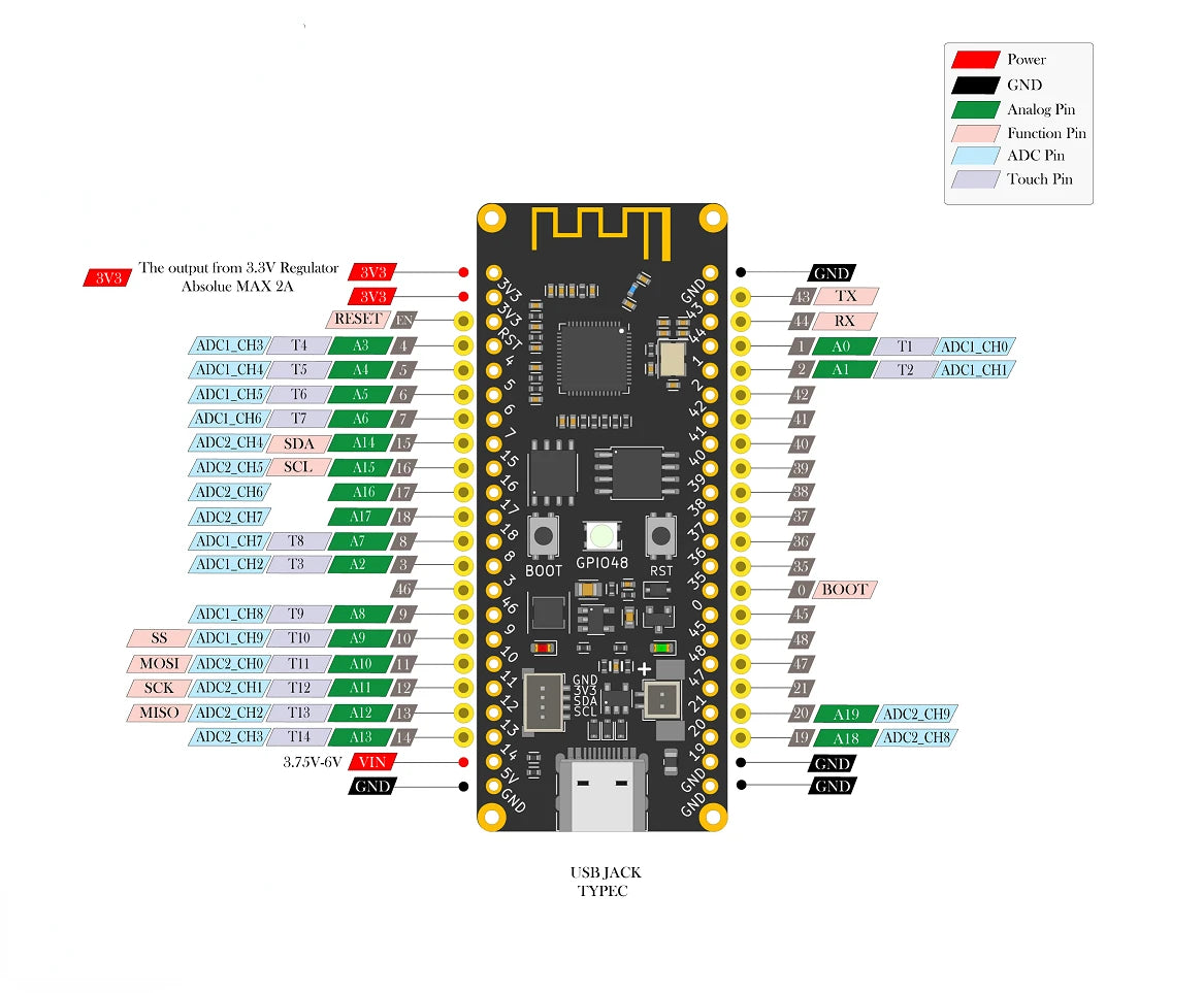
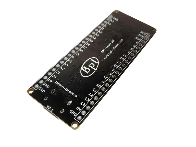
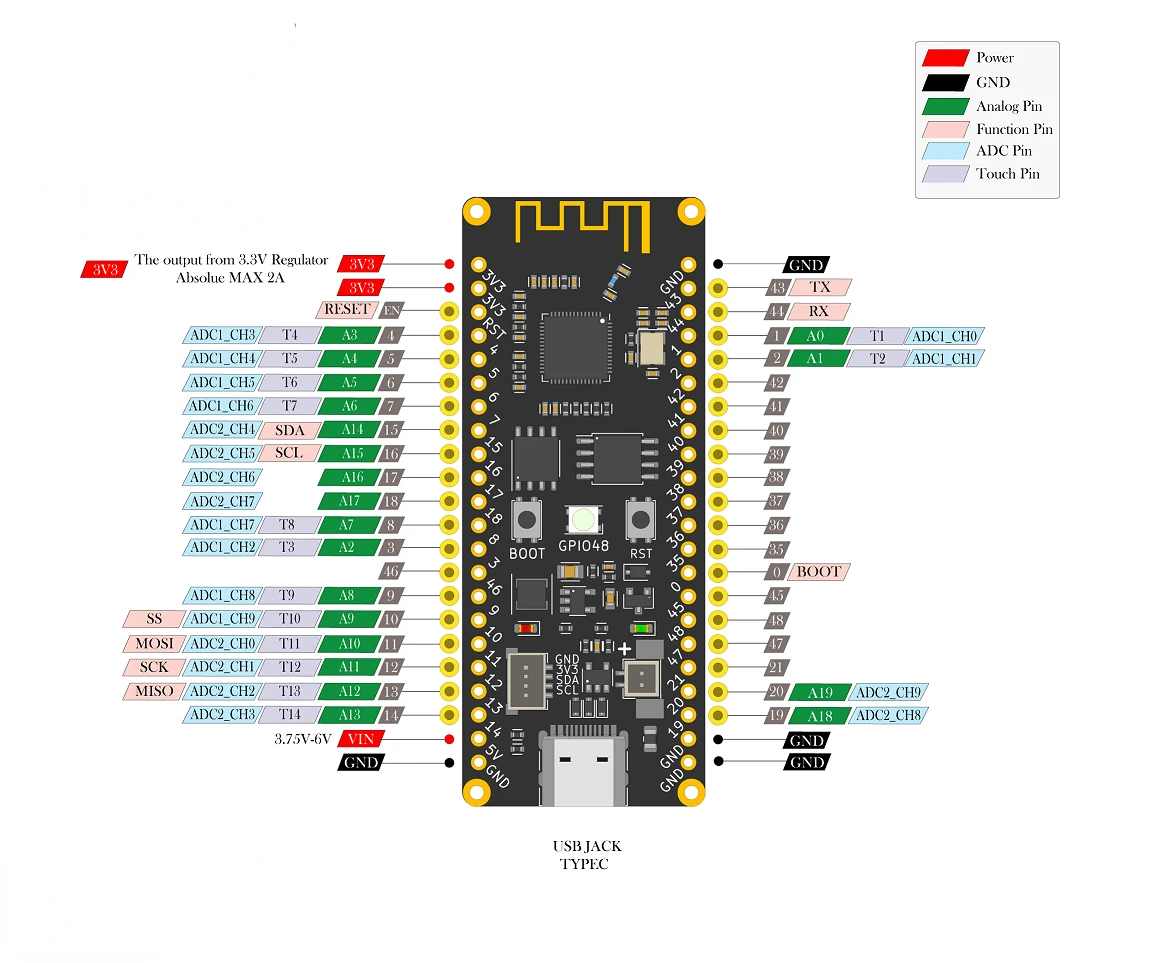
All IO pins corresponding to the chip are marked on the development board, and the order of the IO pins is consistent with the Espressif ESP32-S3-DevKitC-1 development board. Developers can add peripherals supported by DevKitC-1 to the On the S3, the development board can also be plugged into the breadboard.
Feature
-
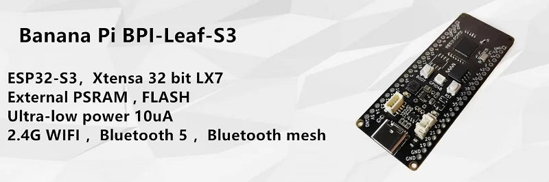
ESP32-S3, Xtensa 32-bit LX7
Off-chip PSRAM , FLASH
Ultra-low power 10uA
2.4G WIFI, BT 5, BT mesh
GPIO, ADC, TOUCH, PWM, I2C, SPI, RMT, I2S, UART, LCD, CAMERA, USB, JTAG
1* 4pin I2C connector
1*USB Type-C
1 * 2pin battery connector, support charging
1 * Full Color LED
| Board | BPI-Leaf-S3 | ESP32-S3-DevKitC-1 |
| GPIO | 36 | 36 |
| 3.3v | 2 | 2 |
| 5v | 1 | 1 |
| GND | 4 | 4 |
| LED light | 1 on GPIO48 | 1 on GPIO48 |
| USB | Type-C USBx1 | MicroUSBx1 |
| UART TTL toUSB | No | CP2102-MicroUSBx1 |
| Battery | 3.7v | NO |
| battery | 500mA | NO |
| I²C 4pin | 1 | No |
The number, sequence and spacing of IO pins of the S3 development board are the same as those of the Espressif ESP32-S3-DevKitC-1 development board.
The B development board no longer has the traditional UART TTL to USB adapter chip and its USB interface. This is because the built-in USB function of the ESP32-S3 chip is perfect enough to support the CDC-ACM virtual serial port and JTAG adapter functions, and no external interface is required. The adapter chip can realize software development and debugging, firmware download and other functions.
Compared with the ESP32-S3-DevKitC-1 development board, the S3 development board adds an external battery connector and is equipped with a charging circuit, which can directly charge the battery through USB, and can automatically switch the power supply, that is, when there is a 3.7v lithium Under the condition of battery, plugging and unplugging the USB will not cause program interruption, which is suitable for more application scenarios.
An I²C 4pin connector is also added to the S3 development board, which makes it more convenient and stable to connect the development board to some I²C devices. In fact, this interface is not limited to connecting I²C devices. All devices that can be controlled by a 3.3v line, a GND line, and one or two signal lines can establish communication with the development board through this 4pin connector.
Espressif ESP32-S3
ESP32-S3 is an MCU chip that integrates 2.4 GHz Wi-Fi and BT 5 (LE) and supports Long Range. The ESP32-S3 is powered by an Xtensa® 32-bit LX7 dual-core processor with a main frequency of up to 240 MHz, built-in 512 KB SRAM (TCM), 45 programmable GPIO pins and rich communication interfaces. ESP32-S3 supports larger-capacity high-speed Octal SPI flash and off-chip RAM, and supports user-configured data cache and instruction cache.
The following is a description of the important functions of the ESP32-S3 chip.
-
Supports Wi-Fi + BT 5 (LE) wireless connectivity: ESP32-S3 integrates 2.4 GHz Wi-Fi (802.11 b/g/n) supporting 40 MHz bandwidth; its BT low energy subsystem supports BT 5 (LE) and BT Mesh for long-distance communication via Coded PHY and broadcast extensions. It also supports 2 Mbps PHY for increased transfer speed and data throughput. The ESP32-S3 has superior Wi-Fi and BT LE RF performance and works stably even at high temperatures.
Support for AI acceleration: The ESP32-S3 MCU adds vector instructions for accelerating tasks such as neural network computation and signal processing. AI developers can use these vector instructions through the ESP-DSP and ESP-NN libraries to implement high-performance image recognition, voice wake-up, and recognition applications.
Rich IO interfaces: ESP32-S3 has 45 programmable GPIOs and common peripheral interfaces such as SPI, I2S, I2C, PWM, RMT, ADC, UART, SD/MMC host controller and TWAITM controller. 14 of them can be configured as capacitive touch inputs for HMI interaction. In addition, ESP32-S3 is equipped with an ultra-low power co-processor (ULP), which supports a variety of low-power modes and is widely applicable to various low-power application scenarios.
Perfect security mechanism: ESP32-S3 provides perfect security mechanism and protection measures for IoT devices to prevent various malicious attacks and threats. It supports flash encryption based on AES-XTS algorithm, Secure Boot based on RSA algorithm, digital signature and HMAC. ESP32-S3 also adds a "World Controller" module, which provides two non-interfering execution environments to implement a trusted execution environment or a privilege separation mechanism.
| BPI-Leaf-S3 | |
| SoC chip | ESP32-S3,Xtensa 32 LX7 dual core processor |
| main frequency | 240MHz MAX |
| Operating temperature | -40℃~+85℃ |
| ROM | 384 KB |
| SRAM | 320 KB |
| FLASH ROM | 8MB |
| PSRAM | 8MB |
| WIFI | IEEE 802.11 b/g/n ,2.4Ghz,150Mbps |
| BT | BT 5 ,BT mesh |
| GPIO | 36 |
| ADC | 2 × 12 SAR ADC,Supports 20 analog channel inputs |
| TOUCH | 14 |
| SPI | 4 |
| I2C | 2,Supports master or slave mode |
| I2S | 2,Serial stereo data input and output |
| LCD | 1,Support 8-bit ~16-bit parallel RGB, I8080, MOTO6800 interface |
| CAMERA | 1,Supports 8-bit ~16-bit DVP image sensor interface |
| UART | 3, support asynchronous communication (RS232 and RS485) and IrDA |
| PWM | 8 independent channels, 14-bit precision |
| MCPWM | 2 |
| USB | 1 × USB 2.0 OTG,Type-C |
| USB Serial/JTAG | 1,USB ,CDC-ACM ,JTAG |
| Temperature Sensor | 1,–20 °C to 110 °C, |
| SD/MMC | 1 × SDIO,2,SD3.03.01,SDIO 3.0,CE-ATA 1.1,MMC 4.41,eMMC 4.54.51 |
| TWAI | 1 ,Compatible with ISO11898-1 (CAN Specification 2.0) |
| DMA | 5 receive channels and 5 transmit channels |
| RMT | 4 channels transmit, 4 channels receive, shared 384 x 32-bit RAM |
| pulse counter | 4 4. Each unit has 2 independent channels |
| timer | 4 × 54-bit general-purpose timer, 16-bit clock prescaler, 1 × 52-bit system timer, 3 × watchdog timer |
| External crystal | 40Mhz |
| RTC and low power management | Power Management Unit (PMU) + Ultra Low Power Coprocessor (ULP) |
| Low power consumption current | 10uA |
| Operating Voltage | 3.3V |
| Input voltage | 3.3V~5.5V |
| Maximum discharge current | 2A3.3V LDO |
| USB | Support |
| Maximum charging current | 500mA |
| LED | 1 |
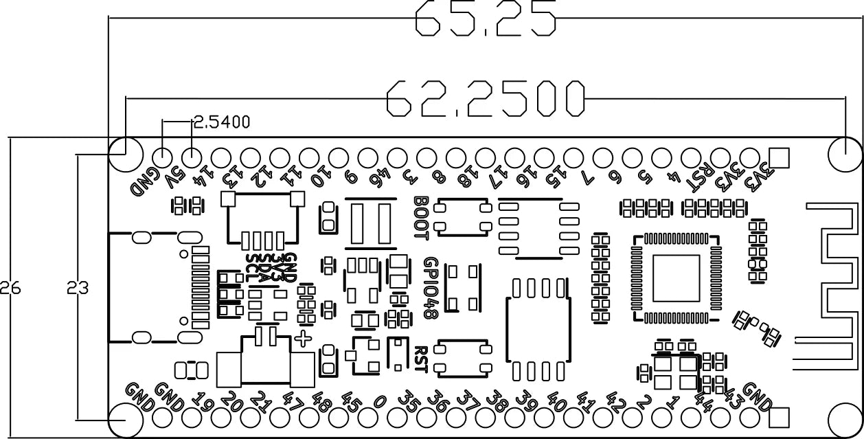
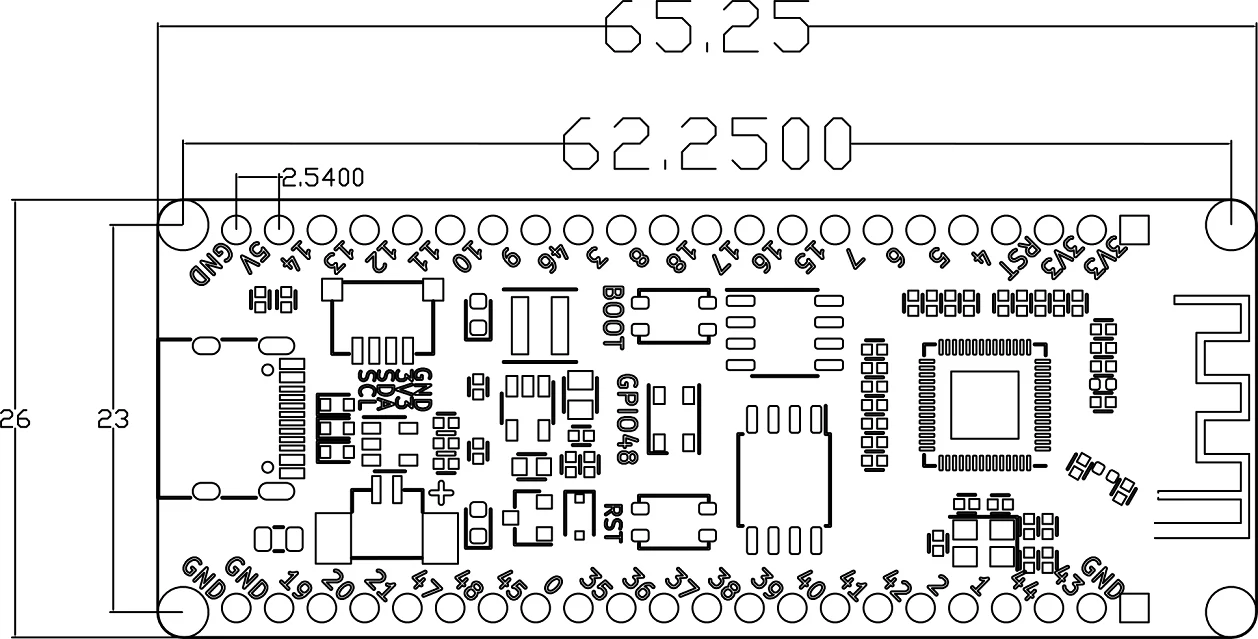
Size
| GPIO pin assignment | ||
| Peripheral interface | Single | Pin |
| ADC | ADC1_CH0~9 | GPIO 1~10 |
| ADC2_CH0~9 | GPIO 11~20 | |
| touch sensor | TOUCH1~14 | GPIO 1~14 |
| JTAG | MTCK | GPIO 39 |
| MTDO | GPIO 40 | |
| MTDI | GPIO 41 | |
| MTMS | GPIO 42 | |
| UART | The pins are assigned by default and can be redefined as any GPIO | |
| U0RXD_in | GPIO 44 | |
| U0CTS_in | GPIO 16 | |
| U0DSR_in | GPIO | |
| U0TXD_out | GPIO43 | |
| U0RTS_out | GPIO 15 | |
| U0DTR_out | GPIO | |
| U1RXD_in | GPIO 18 | |
| U1CTS_in | GPIO 20 | |
| U1DSR_in | GPIO | |
| U1TXD_out | GPIO 17 | |
| U1RTS_out | GPIO 19 | |
| U1DTR_out | GPIO | |
| U2 | GPIO | |
| I2C | GPIO | |
| PWM | GPIO | |
| I2S | GPIO | |
| LCD | GPIO | |
| CAMERA | GPIO | |
| RMT | GPIO | |
| SPI0/1 | FLASHPSRAM | |
| SPI2/3 | GPIO | |
|
| GPIO | |
| USB OTG | D- | GPIO 19( PHY) |
| D+ | GPIO 20( PHY) | |
| VP | GPIO 42( PHY) | |
| VM | GPIO 41( PHY) | |
| RCV | GPIO21( PHY) | |
| OEN | GPIO 40( PHY) | |
| VPO | GPIO 39( PHY) | |
| VMO | GPIO38( PHY) | |
| USB Serial/JTAG | D- | GPIO 19( PHY) |
| D+ | GPIO 20( PHY) | |
| VP | GPIO 42( PHY) | |
| VM | GPIO 41( PHY) | |
| OEN | GPIO 40( PHY) | |
| VPO | GPIO 39( PHY) | |
| VMO | GPIO38( PHY) | |
| SD/MMC | GPIO | |
| MCPWM | GPIO | |
| TWAI | GPIO | |
| LED | GPIO 48 | |