


Lonten Tech
Custom 0.75KW Frequency Converter Electric Inverter 750W RS485 Add Motor Driver MCU 220V Single Phase Input 220V Three-Phase Output Manufacturer
Custom 0.75KW Frequency Converter Electric Inverter 750W RS485 Add Motor Driver MCU 220V Single Phase Input 220V Three-Phase Output Manufacturer
Couldn't load pickup availability
Electric Inverter User Manual
Chapter I Overview
This manual is intended for installation, commissioning, maintenance and use by the user.
------------------------------------------------------------------------------------------------------------------------
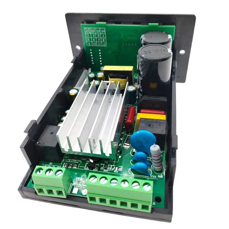
1.Unpacking inspection
Remove the Inverter from the box and confirm that: Whether the product appearance is damaged or
deformed: Whether the components are damaged or fall off: Observe the rating of the nameplate on
the chassis side and check whether it is consistent with your order requirements:
Check whether the items listed in the packing list box are complete. If there is any doubt about the
product damage, please contact the supplier immediately.
------------------------------------------------------------------------------------------------------------------------
2.Please read it carefully before use and keep it properly.
------------------------------------------------------------------------------------------------------------------------
3.Use environment.
Power supply : Single input AC220V±40%
Temperature: -10℃- 50℃
Humidity: 0% - 65%
------------------------------------------------------------------------------------------------------------------------
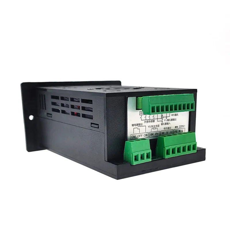
4.Precautions
When wiring, the power supply must be turned off.
Make sure that AC power is never connected to the motor output.
------------------------------------------------------------------------------------------------------------------------
5.There is no condensation, dust and corrosive liquid/gas on the site.
------------------------------------------------------------------------------------------------------------------------
6.The installation position shall be firm and free from vibration.
------------------------------------------------------------------------------------------------------------------------
7.As the overall size is small, please handle the wire ends properly.
------------------------------------------------------------------------------------------------------------------------
8.If the ambient temperature is high, please leave enough heat dissipation space.
------------------------------------------------------------------------------------------------------------------------
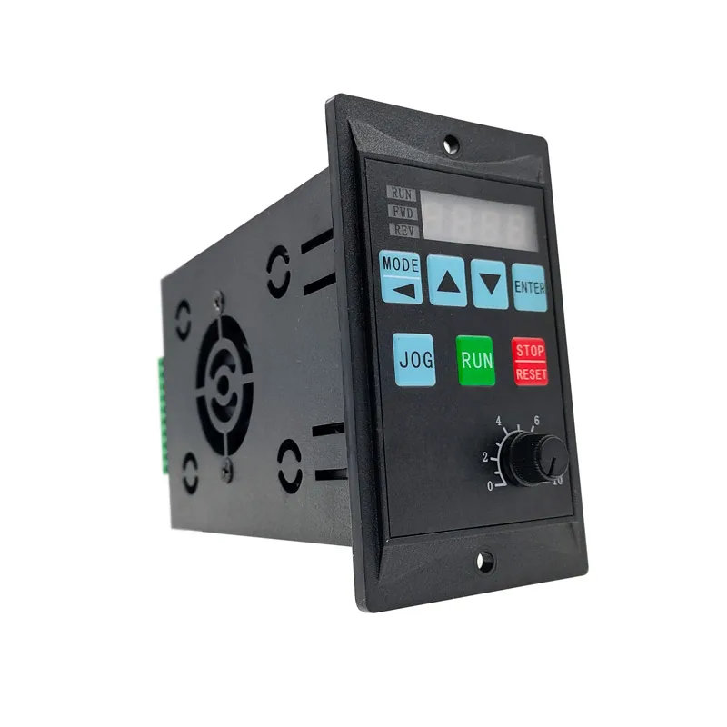
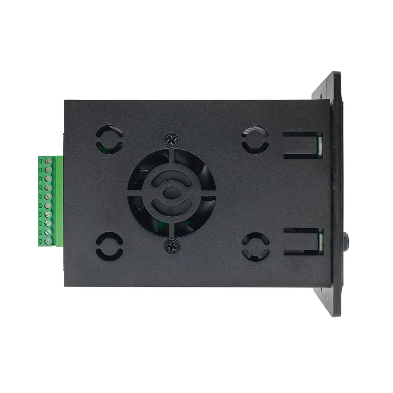
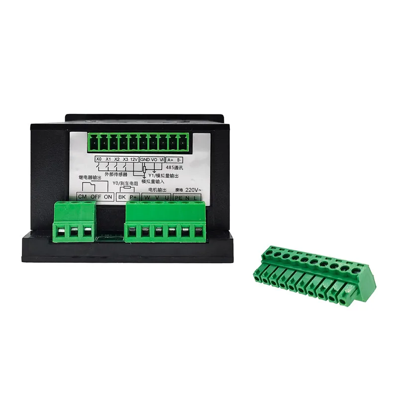
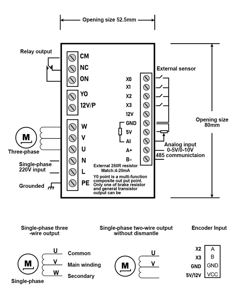
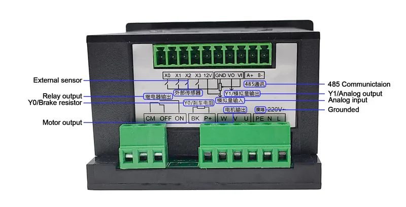
Chapter II Installation and wiring
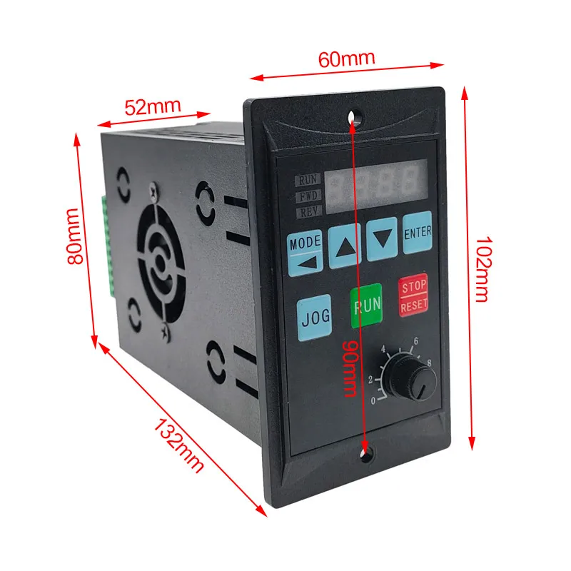
Opening size: 52.5mm*80mm*130mm
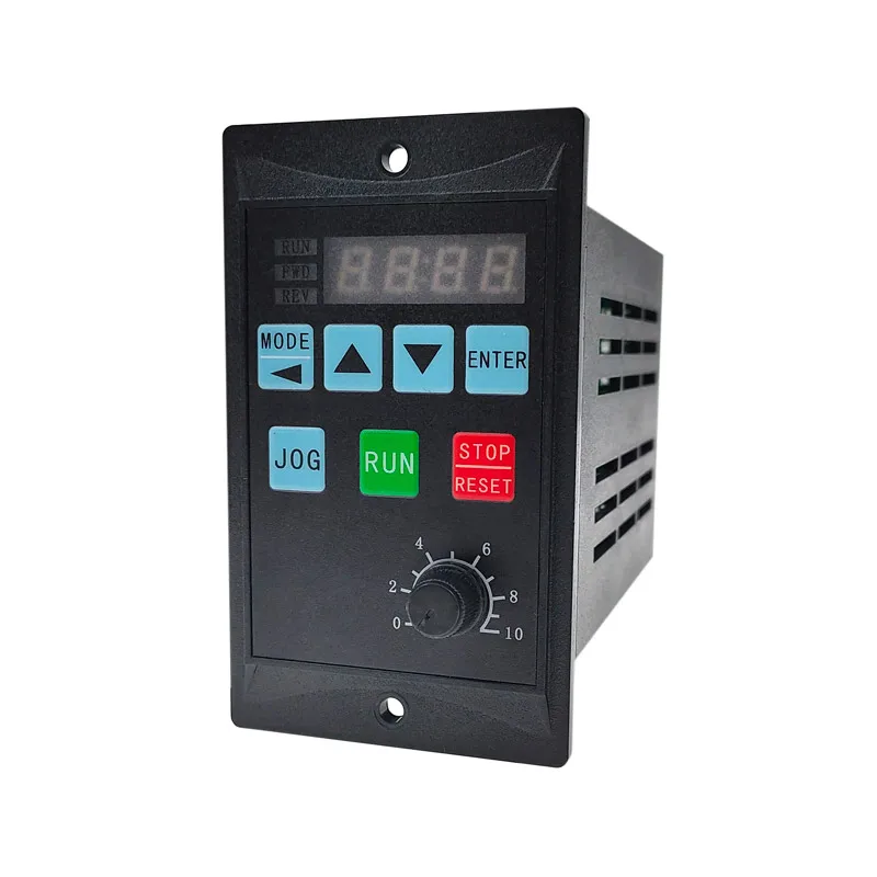
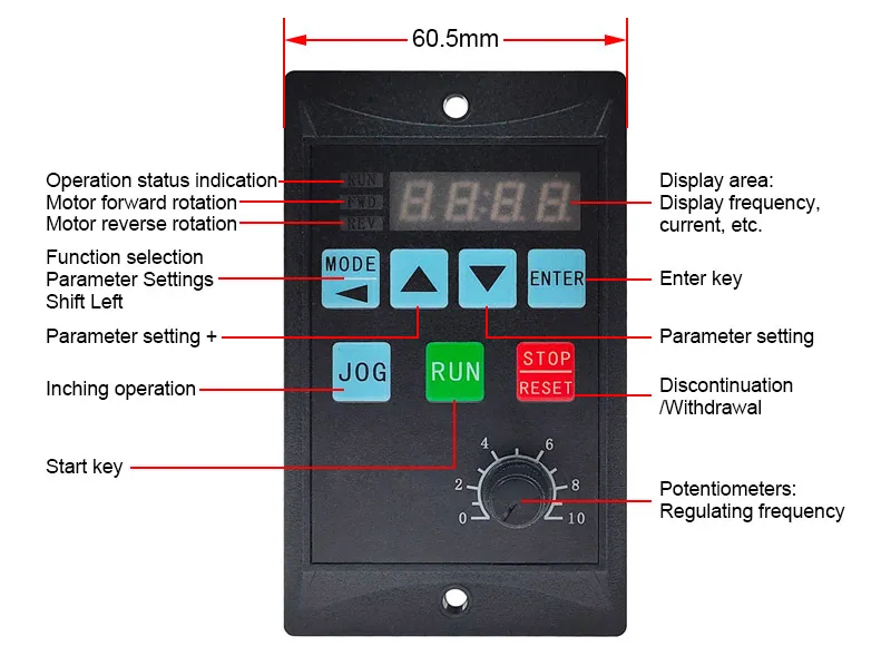
Chapter III Key Description:
XXX below represents arbitrary data
------------------------------------------------------------------------------------------------------------------------
(MODE key):
This key can view the set frequency (Fxxx) and operating frequency (Hxxx) of the frequency converter.
Operating current (Axxx), motor direction (FWD/REV), input voltage (Uxxx), inverter temperature (TXXX),
Input point status (Lxxx), PID parameter display (X.X-X X) indicates set point / feedback value.
------------------------------------------------------------------------------------------------------------------------
(▲key):
Add data function when setting data or add frequency when frequency is controlled by panel.
------------------------------------------------------------------------------------------------------------------------
(▼key):
Subtract data function when setting data or reduce frequency when frequency is controlled by panel.
------------------------------------------------------------------------------------------------------------------------
(ENTER key):
Press this key to enter parameter mode when entering Pxxx parameter setting, and press this key to
save the set parameters after modification.
------------------------------------------------------------------------------------------------------------------------
(JOG key):
Jog operation function.
------------------------------------------------------------------------------------------------------------------------
(RUN key):
Inverter panel operation start key.
------------------------------------------------------------------------------------------------------------------------
(STOP/RESET key):
Press this key to stop in operation mode, and press this key to clear fault alarm function in fault display
mode.
------------------------------------------------------------------------------------------------------------------------
(ENTER+):
This key is a composite key. In panel lock mode, you can press this key to unlock the function. When
the panel lock function is enabled, you can press this key to enter the panel lock function.
------------------------------------------------------------------------------------------------------------------------
Description of panel settings:
When the panel displays Pxxx, you can press the up and down arrow buttons to adjust to the specified
parameter number, and then press the ENTER key to enter the data mode of this menu item. This data
can be modified to the specified size according to the following table. After modification, press the
ENTER key to save. If the panel does not display Pxxx mode, you can press the MODE key until Pxxx
is displayed.
------------------------------------------------------------------------------------------------------------------------
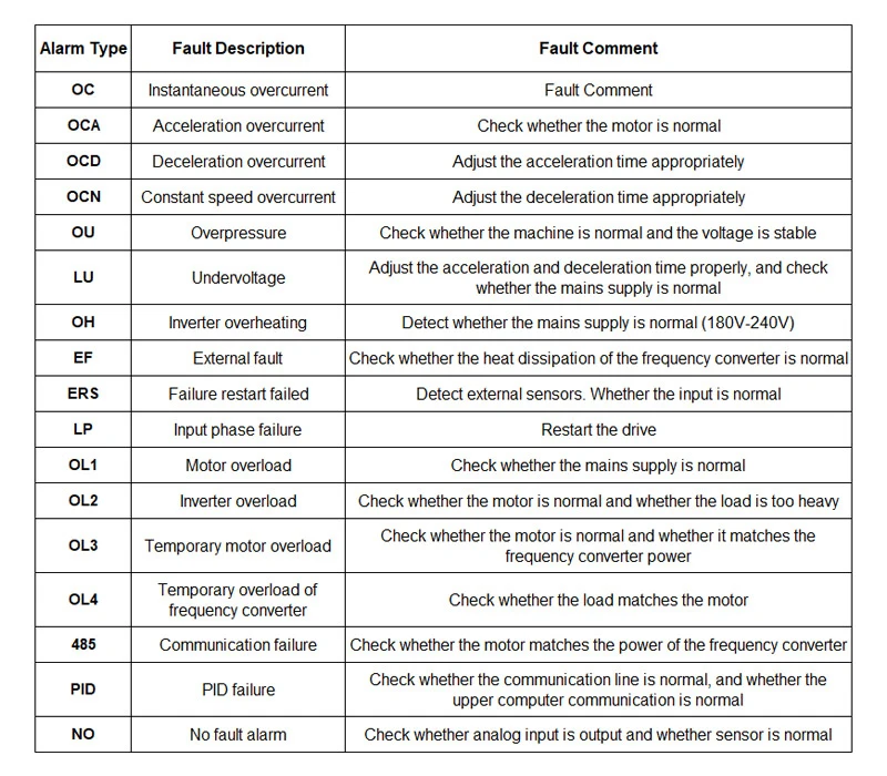
Chapter IV Fault Code